


J) Repeat this test on Q1, Q2, Q3 as well.
if the signal is not
present there could be a fault in the IGBT driver circuit,
specifically ISO1 and ISO2 (
), or in the control board (
, in which case we recommend replacing the board).
K) Switch off the HV and replace the 2 fastons connecting the
primary board and the power transformer (CN3 and CN10).
L) Switch on the HV and the variac (initially set to 0V), close the
main power supply switch on the machine and gradually
increase the voltage generated by the variac until it reaches
26Vac.
M) Set up the oscilloscope with the voltage probe x100
connected between the collector (probe) and the emitter
(earth) of IGBT Q4 on the primary board (
).
N) Make sure the waveform shown on the oscilloscope
resembles
O) Repeat this test on Q2 as well, using the differential probe.
If the signal is not present there may be a fault in the IGBT's
(
).
P) Return the variac voltage to 0V, switch off the machine and the
HV power supply.
Q) Disconnect the HV power supply, replace jumper JP1 on the
board.
R) Switch the machine on again and gradually increase the
voltage generated by the variac to 150Vac 5% then make sure
an alarm is registered with yellow LED D8 on and alarm “AL.1”
shown on the display.
S) Increase the voltage on the variac to 230Vac and make sure
the alarm ceases (yellow LED D8 goes off).
T) Increase the voltage on the variac yet again to 300Vac 5% and
make sure the machine registers an alarm again. Return the
variac voltage immediately to 230Vac and switch off the
machine.
if an alarm persists (and is not caused by a fault in the control
board) there could be a fault in opto-isolator ISO3 or integrated
circuit U3 on the primary board (
).
N.B.
fig. 5
fig.
3
fig. 5
fig. E.
N.B.
fig.5
N.B.
fig. 3
7.0 Repairs, replacing the boards
If repairing the board is complicated or impossible, it should be
completely replaced.
The board is identified by a 6-digit code (printed in white on the
component side after the initials TW). This is the reference code
for requesting a replacement: Telwin may supply boards that are
compatible but with different codes.
before inserting a new board check it carefully for
damage that may have occurred in transit. When we supply a
board it has already been tested and so if the fault is still present
after it has been replaced correctly, check the other machine
components. Unless specifically required by the procedure, never
alter the board trimmers.
If the fault is in the control board remove it from the primary board
as follows:
-
with the machine disconnected from the main power supply
disconnect all the wiring from the control board;
-
cut any bands restricting the board;
-
remove the control board from the spacers attached to the
primary board;
for assembly proceed in the reverse order.
If the fault is in the control board we strongly advise replacing it
without further intervention.
If the fault is in the primary board remove it from the machine
structure as follows:
-
with the machine disconnected from the main power supply
and after removing the control board, disconnect all the wiring
from the primary board;
-
cut any bands restricting the board (e.g. on the power supply
cable and primary connections);
-
undo the screws fastening the front and back panels and
remove the panels from the machine structure;
-
undo the screws fastening the primary board to the machine
structure;
-
remove the primary board by lifting it upwards.
for assembly proceed in the reverse order.
The 4 IGBT's are attached to 2 different dissipators and whenever
a replacement is required, both IGBT's should be replaced.
Before making the replacement make sure the components
piloting the IGBT's are not also damaged:
-
with the multimeter set in
mode make sure there is no
short circuit on the PCB between the 1 and 3 bump contacts
(between gate and emitter) corresponding to each
component;
-
alternatively, resistors R3, R4, R7, R8 could have burst and/or
diodes D11, D12, D15, D16 may be unable to function at the
correct Zener voltage (this should have shown up in the
preliminary tests);
-
clean any irregularity or dirt from the dissipators. If the IGBT's
have burst the dissipators may have been irreversibly
damaged: in this case they should be replaced;
-
apply thermo-conductive grease following the general
WARNING!
N.B.
N.B.
Please read the procedure for replacing the IGBT's
carefully: (fig. 5).
ohm
7.1 Removing the control board (fig. 3)
7.2 Removing the primary board (fig. 3)
-
Unscrew the four (4) nuts that fix the dissipator onto the
card;
-
unscrew the four (4) screws that fix the four (4) IGBT onto
the dissipator;
-
unscrew the two (2) screws that fix the two diode bridges
onto the dissipator;
-
remove the four (4) IGBT and the two (2) diode bridges by
unwelding the reophores, then remove tin from the
printed plates;
-
remove dissipator from card.
st
rd
- 17 -
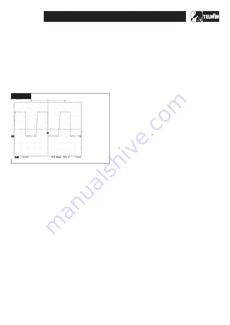
TECHNOLOGY TIG 172 AC/DC
SETTINGS:
· PROBE x10;
· 10V/Div;
· 5 sec/Div.
±
.
· AMPLITUDE IS:
35V ±20%.
µ
TIME TOLLERANCE 20%.
VERIFY THAT
FIGURE E
Содержание TECHNOLOGY TIG 172
Страница 7: ... 7 TECHNOLOGY TIG 172 AC DC WIRING DIAGRAMS General wiring diagram ...
Страница 8: ... 8 TECHNOLOGY TIG 172 AC DC Wiring diagram primary board Power Wiring diagram primary board Driver ...
Страница 10: ... 10 TECHNOLOGY TIG 172 AC DC Wiring diagram control board Digital Wiring diagram control board Analogyc ...
Страница 11: ... 11 TECHNOLOGY TIG 172 AC DC Wiring diagram control board In Out Wiring diagram secondary board Power ...


