


J15 and J16 from the control board and make sure the
resistance is approx. 0ohm (
).
-
thermostat continuity test on secondary dissipator:
disconnect fastons J13 and J14 from the control board and
make sure the resistance is approx. 0 ohm (
).
Switch on the HV power supply (HV OUT) and make sure that
(fig. 5):
-
pre-charge relays K1 and K2 close;
-
the fan starts to turn for the power transformer;
Make sure the waveform shown on the oscilloscope
resembles
.
if there is no signal it may be necessary to replace the
integrated circuit U2 or IGBT Q10 on the primary board (
).
C) Set up the multimeter in volt mode and make sure the primary
board has the following voltages: (
):
-
between the cathode of diode D32 (+) and the negative of
diode bridge D5 (-): equal to +16.5Vdc 3%;
- between pin 3 (+) and the dissipator (-) of U5: equal to +5Vdc
5%;
- between pin 3 (+) and the dissipator (-) of U4: equal to +12Vdc
5%;
- between pin 3 (+) and pin 1 (-) of U6: equal to -12Vdc 5%;
- between pin 8 (+) and pin 7 (-) of ISO1: equal to +30Vdc 5%;
- between pin 8 (+) and pin 7 (-) of ISO2: equal to +30Vdc 5%;
- between pin 4 (+) and pin 5 (-) of J4: equal to +18Vdc 10%;
- between pin 9 (+) and pin 8 (-) of J4: equal to +18Vdc 10%;
D) Switch off the HV power supply, reposition the control board
and reconnect the wiring.
E) On the front panel set switch SW2 to MMA (as low as it will go)
and switch SW3 to DC-LIFT (in the centre).
F) Switch on the HV power supply (HV out) and make sure that
(fig. 2A):
- the green power supply LED D6 lights up;
- the green LED D7 indicating voltage over the torch lights up;
- the yellow alarm LED D8 is off;
- the display shows a numeric value that varies between 5 and
140 when the encoder is turned.
- with the oscilloscope probe connected as in point 6.1 F) the
wave form resembles
;
- the frequency is equal to 60KHz ±5%; if the frequency reading
on the oscilloscope is not 60KHz ±5%, calibrate the frequency
when the machine is being tested (see point 1.2 A).
if the signal is not present it may be necessary to replace the
integrated circuit U2 or IGBT Q10 on the primary board
G) Switch off the HV power supply.
H) Set up the oscilloscope with the voltage probe x10 connected
between the gate (probe) and the emitter (earth) of IGBT Q4
on the primary board
).
I) Switch on the HV power supply (HV out) and make sure the
waveform displayed on the oscilloscope resembles
.
fig. 7
fig. 7
A)
B)
Fig. B
N.B.
fig. 5
fig. 5
fig. C
N.B.
(fig. 7).
(fig. 5
fig. D
6.0 Electrical measurements with the machine in
operation
WARNING!
fig. 3
fig. 4
fig. 5
WARNING!
Before proceeding with faultfinding, we should
remind you that during these tests the power source is powered
and therefore the operator is exposed to the danger of electric
shock.
The tests described below can be used to check the operation of
the power and control parts of the power source.
A) Do not connect the gas mixture source.
B) Disconnect all connectors and fastons from the control board
and remove it from the primary board.
C) From the primary board, disconnect fastons CN3 (XF+) and
CN10 (XF-) for the power transformer (
), and disconnect
faston J1 from the support board (fig. 5).
D) On the primary board disconnect the jumper on JP1.
E) Connect the HV power supply OUT (code 802403) on the
primary board as follows (
):
-
(+) Positive (clamp) to rheofore of resistor R35 towards
JP1 (after removing jumper JP1);
-
(-) Negative (faston) to negative faston of diode bridge D3.
F) Set up the oscilloscope with the voltage probe x100
connected between the rheofore of R40A (collector Q10)
towards JP1 (probe) and the negative of diode bridge D3
(earth) to the primary board (
).
G) Disconnect fastons J1 and J3 from the HF board (fig. 4).
H) Connect the power supply cable to a single phase variac with
variable output 0-300 Vac.
during testing prevent contact with the metal part of
the torch because of the presence of high voltages that are
hazardous to the operator.
6.1 Preparation for testing
6.1 Scheduled tests
only
- 16 -
TECHNOLOGY TIG 172 AC/DC
SETTINGS:
· PROBE x10
· 100mV/Div;
· 10 sec/Div.
VERIFY THAT:
· THE FREQUENCY IS
60KHz ±10%;
· AMPLITUDE IS
450V ±10%.
µ
FIGURE C
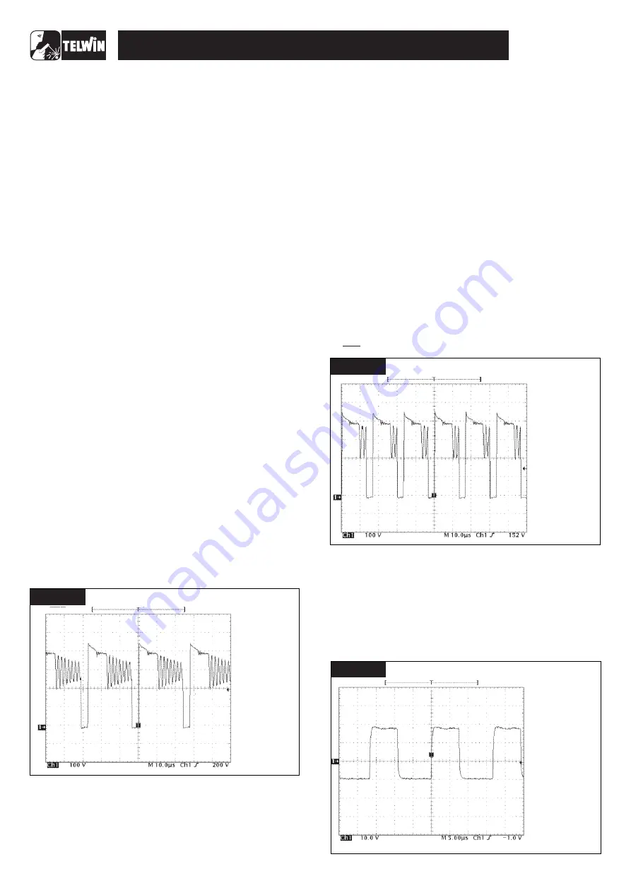
SETTINGS:
· PROBE x100;
· 100 V/Div;
· 10 sec/Div.
· THE FREQUENCY
IS 35KHz ±15%;
· AMPLITUDE IS
450V ±10%;
µ
VERIFY THAT
FIGURE B
SETTINGS:
· PROBE x10;
· 100mV/Div;
· 5 sec/Div.
TIME TOLLERANCE ± 20%
· POSITIVE AMPLITUDE
IS +18V ±10%;
· NEGATIVE AMPLITUDE
IS -10V ±10%.
µ
VERIFY THAT
FIGURE D
Содержание TECHNOLOGY TIG 172
Страница 7: ... 7 TECHNOLOGY TIG 172 AC DC WIRING DIAGRAMS General wiring diagram ...
Страница 8: ... 8 TECHNOLOGY TIG 172 AC DC Wiring diagram primary board Power Wiring diagram primary board Driver ...
Страница 10: ... 10 TECHNOLOGY TIG 172 AC DC Wiring diagram control board Digital Wiring diagram control board Analogyc ...
Страница 11: ... 11 TECHNOLOGY TIG 172 AC DC Wiring diagram control board In Out Wiring diagram secondary board Power ...


