Telonics TCA-500C Combo Amp
42
PB-009289 Rev E
(O
PTIONAL
)
E
XTERNAL
C
ONTROL
U
NIT
(C
ONTINUED
)
C
ONTROLLING THE
L
EXICON
MX-200
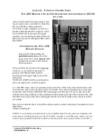
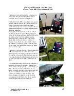
The External Control Unit provides two (2) momentary push button switches which may be used
to either ENABLE (UN bypass), or DISABLE (bypass) the two effect “engines” in the Lexicon
MX-200 effects unit.
A second ¼ inch TRS stereo cable is required to connect the Lexicon MX-200 side of the
External Control Unit (the LEFT side). The cable for this connection is all black in color. Be sure
this cable is fully inserted into the bottom LEFT side of the Remote Control Unit, with the TRS
stereo plug on the other end of the cable plugged into the FOOTSWITCH jack on the left side of
the rear panel of the MX-200 EFX unit.
The two ¼ inch TRS stereo cables used for connection are available from Telonics.
Momentarily depressing these two buttons does exactly the same thing as depressing the two
BYPASS buttons on the front panel of the MX-200. You can determine the status by looking at
the LED indicators within the BYPASS buttons on the MX-200.
The controls for the two (2) effects processors in the MX-200 are grouped together in adjacent
rectangular “boxed” areas on the front panel of the MX-200. Each “box” contains a BYPASS
button in the upper right corner, three control/function/parameter knobs, a tempo button and a
UP/DOWN toggle switch which is used to select the desired effect (which that particular
processor “engine” will be generating.
Processor Number 1 is on the LEFT. Its BYPASS button has a GREEN LED in it. This
processor is normally used to generate DELAYS and similar effects.
Processor Number 2 is on the RIGHT. Its BYPASS button has a RED LED in it. This processor
is normally used to generate REVERBS and similar effects.
NOTE!
It is necessary to comprehend that when the LED in a given BYPASS button is ON,
that processor is BYPASSED, meaning that the effect being generated by that
process is OFF!
I.E., when a given BYPASS button LED is ON, the effect is OFF!
The two buttons on the LEFT side of the External Control Unit control these BYPASS buttons
just as if you actually pushed the buttons on the MX-200 themselves. The STATUS of the
BYPASS buttons (and therefore the status of the effects processors in the MX-200) is indicated
by the colored LED within the button on the MX-200.
The UPPER/BLACK button on the External Control Unit controls Processor #1 (Green BYPASS
LED on the MX-200).
The LOWER/RED button on the External Control Unit controls Processor #2 (RED BYPASS
LED on the MX-200).
Содержание MINI-12
Страница 14: ...Telonics TCA 500C Combo Amp 14 PB 009289 Rev E ...
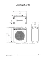
Страница 53: ...Telonics TCA 500C Combo Amp 53 PB 009289 Rev E TCA 500C 15 1U COMBO MECHANICAL OUTLINE DRAWINGS ...
Страница 54: ...Telonics TCA 500C Combo Amp 54 PB 009289 Rev E TCA 500C 12 1U COMBO MECHANICAL OUTLINE DRAWINGS ...
Страница 55: ...Telonics TCA 500C Combo Amp 55 PB 009289 Rev E TCA 500C 15 MINI COMBO MECHANICAL OUTLINE DRAWINGS ...
Страница 56: ...Telonics TCA 500C Combo Amp 56 PB 009289 Rev E TCA 500C 12 MINI COMBO MECHANICAL OUTLINE DRAWINGS ...
Страница 57: ...Telonics TCA 500C Combo Amp 57 PB 009289 Rev E MINI 15 EXTERNAL SPEAKER ENCLOSURE MECHANICAL OUTLINE DRAWINGS ...
Страница 58: ...Telonics TCA 500C Combo Amp 58 PB 009289 Rev E MINI 12 EXTERNAL SPEAKER ENCLOSURE MECHANICAL OUTLINE DRAWINGS ...
Страница 59: ...Telonics TCA 500C Combo Amp 59 PB 009289 Rev E TCA 500C 212 SUPER TWIN COMBO MECHANICAL OUTLINE DRAWINGS ...
Страница 60: ...Telonics TCA 500C Combo Amp 60 PB 009289 Rev E TCA 500C 1U HEAD UNIT MECHANICAL OUTLINE DRAWINGS ...
Страница 62: ...Telonics TCA 500C Combo Amp 62 PB 009289 Rev E ...


