LN930 M.2 Hardware User Guide
1VV0301078 Rev.10 – 2015-11-11
Reproduction forbidden without written authorization from Telit Communications S.p.A. - All Rights Reserved.
Page 60 of 88
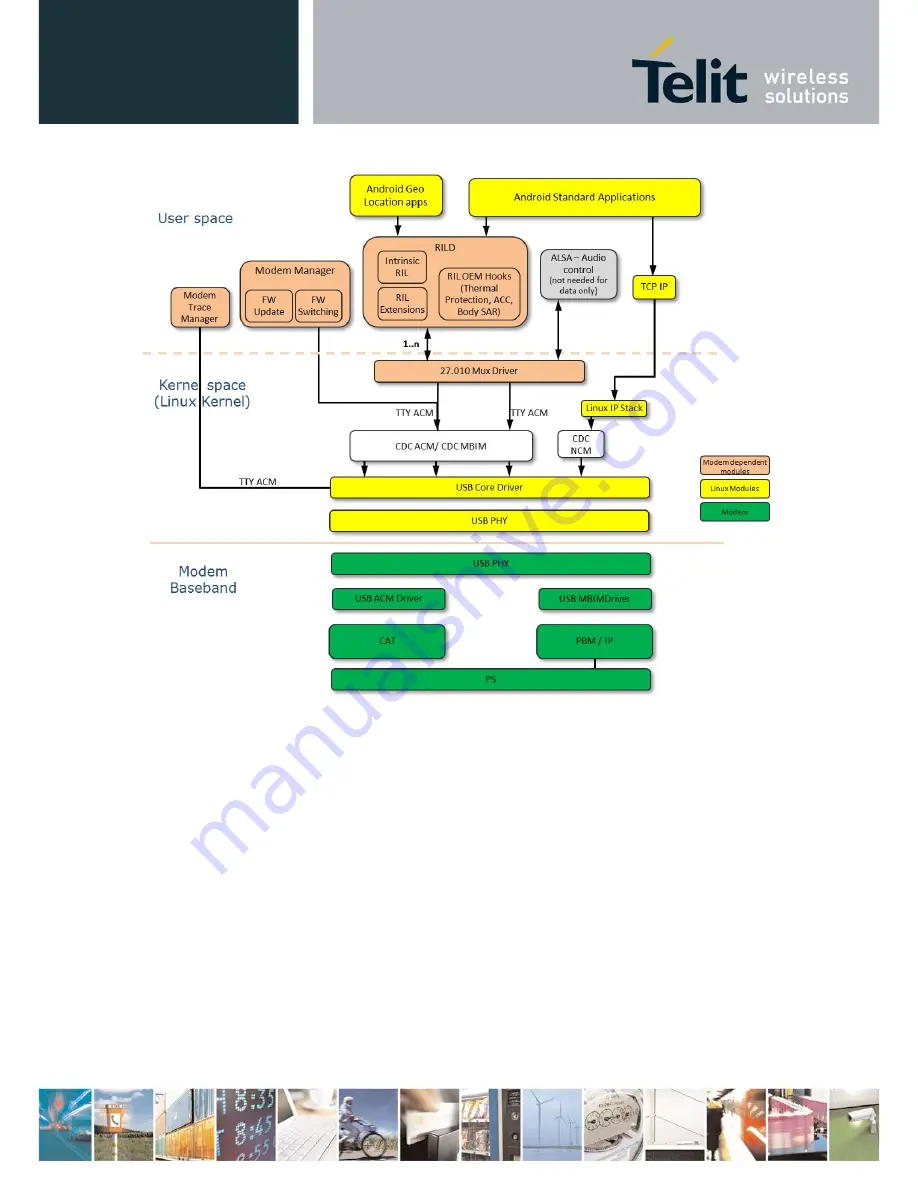
Figure 16 Chrome Software Architecture
Страница 1: ...LN930 M 2 Hardware User Guide 1VV0301078 Rev 10 2015 11 11...
Страница 2: ...Hardware User Guide 1VV0301078 Rev 10 2015 11 11 Reproduction forbidden without written authorization from Telit Communications S p A All Rights Reserved Page 2 of 88 APPLICABILITY TABLE PRODUCT LN930...
Страница 3: ...rve for Telit and its licensors certain exclusive rights for copyrighted material including the exclusive right to copy reproduce in any form distribute and make derivative works of the copyrighted ma...
Страница 4: ...ranslated into any language or computer language in any form or by any means without prior written permission of Telit High Risk Materials Components units or third party products used in the product...
Страница 5: ...ck Diagrams 17 2 2 1 M 2 HN930 Module 17 2 2 2 M 2 LN930 AP Module 19 2 2 3 M 2 LN930 Module 20 2 3 Host Interface Signals 21 3 M 2 Module Interface Details 26 3 1 Interprocessor Interface IPC 26 3 1...
Страница 6: ...4 1 4 RF Calibration 49 4 1 5 Noise Profiling Scan Tool 50 5 Windows Software Components 51 5 1 MBIM Toolkit 54 5 1 1 Windows 7 MBIM driver 54 5 1 2 GNSS UMDF driver for Windows 7 and Windows 8 54 5...
Страница 7: ...Mitigation Adaptive Clocking 66 9 3 Thermal Monitoring 66 9 4 Seamless Roaming Wifi Offload 67 9 5 Conducted Transmit Power 67 9 6 Receiver Sensitivity 68 9 7 Antenna Recommendations 71 9 8 GNSS Sensi...
Страница 8: ...1 11 Reproduction forbidden without written authorization from Telit Communications S p A All Rights Reserved Page 8 of 88 14 4 FCC Class B digital device notice 84 14 5 Radiation Exposure Statement 8...
Страница 9: ...nection 36 Figure 8 Antenna Control Connections Detail 39 Figure 9 In Device Coexistence Architecture 40 Figure 10 RF Antenna Coaxial Connector Location 46 Figure 11 M 2 Carrier Board 48 Figure 12 Win...
Страница 10: ...Control Signals 39 Table 18 Coexistence Hardware Synchronization Signals 41 Table 19 Power Ground Signals 42 Table 20 M 2 Configuration Pins 43 Table 21 Audio Signals Future development 43 Table 22 No...
Страница 11: ...It will also identify the M 2 module application interface along with hardware software reliability and mechanical specifications 1 2 Purpose The intent of this document is to provide design guideline...
Страница 12: ...er two gives an overview of the features of the product Chapter 3 Chapter three describes in details the characteristics of the product Chapter 6 Conformity Assessment Issues provides some fundamental...
Страница 13: ...he standard features of a M 2 Card information on the various SKUs of 2G 3G 4G LTE M 2 modules along with a respective functional block diagram of each SKU 2 1 SKUs 2G 3G LTE M 2 Modules There are fiv...
Страница 14: ...This is the surrounding air temperature of the module inside the platform when the card is fully operating at worst case condition x x x Application Interface 75 pin card Interprocessor Communications...
Страница 15: ...70 MHz x x x x x 002 II 1850 MHz 1910 MHz 1930 MHz 1990 MHz x x x x x 003 III 1710 MHz 1785 MHz 1805 MHz 1880 MHz x x x x 004 IV 1710 MHz 1755 MHz 2110 MHz 2155 MHz x x x 005 V 824 MHz 849 MHz 869 MHz...
Страница 16: ...x 018 XVIII 815 MHz 830 MHz 860 MHz 875 MHz x x 019 XIX 830 MHz 845 MHz 875 MHz 890 MHz x x x 020 XX 832 MHz 862 MHz 791 MHz 821 MHz x 021 XXI 1447 9 MHz 1462 9 MHz 1495 9 MHz 1510 9 MHz x 022 XXII 3...
Страница 17: ...kbps x x x HSPA DL 21 Mbps UL 5 7 Mbps x x x HSPA DL 42 Mbps UL 5 7 Mbps x x LTE FDD DL 100 Mbps UL 50 Mbps x x LTE FDD DL 150 Mbps UL 50 Mbps x x Module supports DL 150 Mbps in LN930 This is only for...
Страница 18: ...M 2 Hardware User Guide 1VV0301078 Rev 10 2015 11 11 Reproduction forbidden without written authorization from Telit Communications S p A All Rights Reserved Page 18 of 88 Figure 1 M 2 HSPA Block Dia...
Страница 19: ...r Intel design based on the XMM 7160 modem platform The module has a targeted area of operation in the Asia Pacific rim and offers 3G and LTE datacard functionality 2G Functionality is not supported T...
Страница 20: ...modem platform The M 2 LTE module is a triple mode 2G 3G and 4G 3GPP release 9 modem providing datacard functionality The M 2 LTE module includes support at the 75 pin application interface for M 2 Co...
Страница 21: ...IO RFE_RFFE_SCLK RFE_RFFE_SDATA Main Switch Duplexer Module B7 Duplexer B7 Div Filter B20 Div Filter Coupler Main Antenna RFE_RFFE_VIO RFE_RFFE_SCLK RFE_RFFE_SDATA PA DCDC RFE_TQ_H RFE_TP_H RFE_TP_L R...
Страница 22: ...available on every M 2 module On those modules the signals at the application interface are not connected on the M 2 module Table 4 M 2 Host Interface Signals Pin Signal Name I O Description Supply 1...
Страница 23: ...n I2S_RX 1 8 V 23 WAKE_WWAN O Wake On WWAN Use by M 2 to wake up host 1 8 V 24 AUDIO2 O PCM Out I2S_TX 1 8 V 25 DPR I Dynamic Power Reduction Body SAR control signal 1 8 V 26 GNSS_DISABLE I Disable GN...
Страница 24: ...nected internally on M 2 53 N C Not connected internally on M 2 54 N C Not connected internally on M 2 55 N C Not connected internally on M 2 56 N C Not connected internally on M 2 57 GND P Ground 58...
Страница 25: ...ommunications S p A All Rights Reserved Page 25 of 88 69 CONFIG_1 O Configuration Status WWAN M 2 Connects to GND internally 70 3 3V P WWAN Supply Pin 3 3 V 71 GND P Ground 72 3 3V P WWAN Supply Pin 3...
Страница 26: ...classes CDC MBIM CDC ACM and CDC NCM The USB Controller is compliant to the USB 2 0 Specification and with the Link Power Management LPM Addendum LPM introduces a new sleep state L1 which significant...
Страница 27: ...thout written authorization from Telit Communications S p A All Rights Reserved Page 27 of 88 Table 5 USB HS Interprocessor Communications Interface Signal Name Description Pin Direction WWAN Voltage...
Страница 28: ...t supported by the WWAN M 2 modules presented in this Product Description It is set aside for future development These signals should be left un connected on the host Table 6 USB SSIC ICP Interface Si...
Страница 29: ...Output SIM Card 34 I O 1 8 V 3 0 V UIM_RESET Reset signal for SIM card 30 O 1 8 V 3 0 V USIM_PWR 1 8 V 3 V Supply for SIM Card 36 O 1 8 V 3 0 V SIM Detect SIM Card Detection 66 I 1 8 V 3 2 1 SIM Desi...
Страница 30: ...the X GOLD Communications Processor on the M 2 module to control the GNSS device The solution offers best in class acquisition and tracking sensitivity TFF and accuracy The GNSS device supports sever...
Страница 31: ...production forbidden without written authorization from Telit Communications S p A All Rights Reserved Page 31 of 88 Figure 6 GNSS Connections and Interface A description of the signals between the X...
Страница 32: ...PA Blanking EXT_FRM_SYNC X GOLD baseband provides a strobe signal to the GNSS device to allow fine time assistance based on 3GPP cell timing The GNSS signals available to the host at the WWAN module i...
Страница 33: ...igns Ultrabook host should deliver a 1 8V signal to turn on the module If 1 8V is not feasible recommend using a 47k series resistor connected to 3 3V 6 I 1 8 V RESET Reset the WWAN system This signal...
Страница 34: ...DISABLE is not asserted or in a high impedance state the radio may transmit if not disabled by other means such as software The operation of the W_DISABLE Signal is Enable ON 3 3V The radio transmitte...
Страница 35: ...ditions etc Once those procedures are complete the WWAN module will switch off the RF Radio enable duration On reception of a hardware or software enable signal the WWAN module will initiate within on...
Страница 36: ...tform system using 3 3 V The series resistor can be adjusted to obtain the desired brightness Figure 7 Typical LED Connection The indication protocol for the LED is shown in Table 14 Table 14 LED Stat...
Страница 37: ...AN M 2 module has the ability to configure RF TX power levels based on proximity sensor input from the host A WWAN M 2 power control API is available to the host to dynamically reduce RF transmit powe...
Страница 38: ...1 Reproduction forbidden without written authorization from Telit Communications S p A All Rights Reserved Page 38 of 88 Table 16 DPR SAR Support Signal Signal Name Detailed Description Pin Direction...
Страница 39: ...different frequency responses for the main antenna A sample block diagram depicting the antenna control signal connections to the antenna switch is shown in Figure 8 Intel s current antenna control s...
Страница 40: ...n in Figure 6 Application Processor apps coexistence interface Connectivity Chip WLAN BT GNSS NRT Coexistence interface RT Coexistence interface X GOLD 716 apps coexistence interface NRT Coexistence i...
Страница 41: ...operations do not impact each other significantly The Non Real Time mechanism implements a messaging based interface formatted as AT commands that are passed to the AP host over the IPC interface USB...
Страница 42: ...sing on the communications card The 3 3 V power and ground pins are listed in Table 19 Section 8 Power Delivery Requirements provides electrical requirements for the power supply and I O signals Table...
Страница 43: ...resistor Table 20 M 2 Configuration Pins Signal Name Description Pin Direction WWAN Voltage Level CONFIG_0 This signal is not connected to the WWAN M 2 module 21 O CONFIG_1 Tied to Ground internally o...
Страница 44: ...Guide 1VV0301078 Rev 10 2015 11 11 Reproduction forbidden without written authorization from Telit Communications S p A All Rights Reserved Page 44 of 88 AUDIO2 PCM Out I2S_ TX 24 O 1 8 V AUDIO3 PCM S...
Страница 45: ...exed between the Diversity receiver and GPS receiver if applicable Further details on the antenna connector assignment can be found in Section 11 3 The antenna signals are not available at the host in...
Страница 46: ...dware User Guide 1VV0301078 Rev 10 2015 11 11 Reproduction forbidden without written authorization from Telit Communications S p A All Rights Reserved Page 46 of 88 Figure 10 RF Antenna Coaxial Connec...
Страница 47: ...he hardware and software tools for M 2 development are summarized below 4 1 Carrier Board The M 2 Carrier Board shown in Figure 11 is Intel Mobile Communications hardware platform to facilitate the te...
Страница 48: ...11 M 2 Carrier Board 4 1 1 FlashTool Intel Mobile Communications provides a utility program called FlashTool for downloading a binary image into the Flash memory of the M 2 module The USB HS port or U...
Страница 49: ...B or over a dedicated high speed MIPI trace interface Captured trace data includes standard 3GPP IPC messages print statements inserted by developers in the code error messages and core dump crash inf...
Страница 50: ...utinely offer multiple hardware configurations for the same base model with different processor speed drive type or display type etc Each configuration has a different Radio Frequency emission profile...
Страница 51: ...hird party connection manager utilized Independent Hardware Vendor IHV provided MBIM driver In the Windows 8 architecture Microsoft requirements o MBIM interfaces o User Mode Driver Framework UMDF dri...
Страница 52: ...Hardware User Guide 1VV0301078 Rev 10 2015 11 11 Reproduction forbidden without written authorization from Telit Communications S p A All Rights Reserved Page 52 of 88 Figure 12 Windows 7 Software Arc...
Страница 53: ...Hardware User Guide 1VV0301078 Rev 10 2015 11 11 Reproduction forbidden without written authorization from Telit Communications S p A All Rights Reserved Page 53 of 88 Figure 13 Windows 8 Software Arc...
Страница 54: ...ation enabling the consumer whose Ultrabook or tablet is hosting an Intel M 2 module to update the firmware on WWAN module by executing a graphical application based on NET4 framework The same applica...
Страница 55: ...USB port which is the only available functional interprocessor communications IPC interface at run time and takes into account only the AT control plane and IP packets data connection Audio packet ex...
Страница 56: ...nterface towards application is called UTA Serial interface The application in our case is the AT command handler called C AT The control channel is using AT commands A detailed list of all supported...
Страница 57: ...AT commands 3GPP 27 010 Multiplexer Tracing Connection to test framework The ACM channels are connected via UTA Terminal to S IO and from there via UTA Serial to the application on modem side 6 4 2 Ne...
Страница 58: ...spend Resume and Remote Wake up The PC can set the modem into USB suspend state to save battery power when no communication takes place or when the PC is switched into standby mode The suspend state a...
Страница 59: ...ponents A preliminary view of the software components of a WWAN M 2 module running the Chrome operating system is shown in Figure 16 The architecture is still in development however it is expected tha...
Страница 60: ...2 Hardware User Guide 1VV0301078 Rev 10 2015 11 11 Reproduction forbidden without written authorization from Telit Communications S p A All Rights Reserved Page 60 of 88 Figure 16 Chrome Software Arch...
Страница 61: ...e with 3GPP specification shall be 10 C to 55 C Normal 55 C to 70 C Extreme Extreme is the surrounding air temperature of the module inside the platform when the card is fully operating at worst case...
Страница 62: ...upply provided by the host platform are listed below Table 25 M 2 Module Power Delivery Requirements Ultrabook Requirement Detailed Description Supply voltage 3 3 V at the Card connector will be withi...
Страница 63: ...OL Output Low Current for Open drain Signals Applies to the LED pins 0 4 V 9 mA IIN Input Leakage Current 0 V to 3 3 V 10 10 A ILKG Output Leakage Current 0 V to 3 3 V 50 50 A CIN Input Pin Capacitanc...
Страница 64: ...y 8 1000 mW 2201 mW LTE UTP Cat 3 20 MHz 100 RB APAC SKU only 9 1175 mW 2244 mW LTE UTP Cat 3 10 MHz 50 RB APAC SKU only 11 1073 mW 2155 mW LTE UTP Cat 3 15 MHz 75 RB APAC SKU only 18 1122 mW 1911 mW...
Страница 65: ...at 14 QAM64 M 2 HSDPA Band 1 813 mW Standby Power UMTS Stand by current DRX7 16NB cells 6 mW UMTS Stand by current DRX7 16NB cells HN930 6 6 mW Table 31 GSM Power Consumption GSM Use Case Band Transmi...
Страница 66: ...onent of platform launch One of the key elements of platform noise commonly referred to as RF interference is LCD display panel pixel clock and its harmonics The pixel clock generates RF that translat...
Страница 67: ...ends needed for the EAP SIM functionality are supported In addition all necessary commands need for the PIN entry change and lock unlock are supported Through the API the host can manage Wi Fi Hotspot...
Страница 68: ...Conducted Transmit Power1 E_UTRA class 3 22 5 dBm 0 5 1 db 2 Conducted transmit power as measured at the WWAN M 2 RF main antenna connector 9 6 Receiver Sensitivity The reference sensitivity power le...
Страница 69: ...ain and Diversity ports are measured separately Combining both antenna ports increases sensitivity by 3 dB Table 36 Rx Sensitivity UMTS reflects both ports combined Table 37 Rx Sensitivity LTE HDPA LT...
Страница 70: ...1678 1900 8 FDD QPSK 10 96 3525 3625 3750 9 FDD QPSK 10 96 3850 3975 4099 11 FDD QPSK 10 96 4800 4850 4899 18 FDD QPSK 10 97 5900 5925 5950 19 FDD QPSK 10 97 6050 6075 6100 21 FDD QPSK 10 96 6500 6525...
Страница 71: ...mmon Name Bandwidth of Main Antenna MHz Bandwidth of Diversity Antenna MHz 001 I 1 2100 MHz 1920 MHz to 1980 MHz 2110 MHz to 2170 MHz FDD IMT 250 60 002 II 2 1900 MHz 1850 MHz to 1910 MHz 1930 MHz to...
Страница 72: ...Hz to 862 MHz 791 MHz to 821 MHz FDD EU s Digital Dividend 71 30 021 XXI 21 1500 MHz 1447 9 MHz to 1462 9 MHz 1495 9 MHz to 1510 9 MHz FDD PDC 63 15 4 025 XXV 25 1900 MHz 1850 MHz to 1915 MHz 1930 MHz...
Страница 73: ...iance M 2 module complies with the following listed test standards 3GPP TS 31 121 USIM 3GPP TS 31 124USAT 3GPP TS51 010 1 2G PS RF RRM 3GPP TS 51 010 4 2G SIMTK 3GPP TS34 121 1 3G RF RRM 3GPP TS34 123...
Страница 74: ...3042 S3 B 11 1 Mechanical Dimensions The mechanical dimensions of WWAN Card Type 3042 are shown in Figure 17 and Figure 17 The WWAN card is 30 mm x 42 mm The height is 1 5 mm from the top of the PCB...
Страница 75: ...Hardware User Guide 1VV0301078 Rev 10 2015 11 11 Reproduction forbidden without written authorization from Telit Communications S p A All Rights Reserved Page 75 of 88 Figure 18 WWAN Card 3042 Slot Ke...
Страница 76: ...rbidden without written authorization from Telit Communications S p A All Rights Reserved Page 76 of 88 11 2 Land Pattern Figure 19 illustrates a typical land pattern for a top mount connector with th...
Страница 77: ...ction forbidden without written authorization from Telit Communications S p A All Rights Reserved Page 77 of 88 Figure 20 illustrates a typical mid plane in line land pattern with slot key removed Fig...
Страница 78: ...11 3 Antenna Connector Locations Figure 21 illustrates the locations for the main Rx Tx antenna and the Diversity GPS antenna Figure 21 Antenna Connector Location Table 41 Antenna Connector Assignment...
Страница 79: ...ame cautions have to be taken for the SIM checking carefully the instruction for its use Do not insert or remove the SIM when the product is in power saving mode The system integrator is responsible o...
Страница 80: ...unications S p A dass sich das Ger t 2G 3G module in bereinstimmung mit den grundlegenden Anforderungen und den brigen einschl gigen Bestimmungen der Richtlinie 1999 5 EG befindet Greek Telit Communic...
Страница 81: ...ian Telit Communications S p A izjavlja da je ta 2G 3G modul v skladu z bistvenimi zahtevami in ostalimi relevantnimi dolo ili direktive 1999 5 ES Spanish Por medio de la presente Telit Communications...
Страница 82: ...testing Telit Communications S p A recommends carrying out the following assessments RF spectrum use R TTE art 3 2 It will depend on the antenna used on the final product EMC R TTE art 3 1b Testing H...
Страница 83: ...EMC respectively as well as any relevant Article 3 3 requirements 1 The Dipole antenna gain GPRS EGPRS WCDMA LTE 2dBi was verified in the conformity testing and for compliance the antenna shall not b...
Страница 84: ...this manual CAN ICES 3 B NMB 3 B 14 3 Interference statement This device complies with Part 15 of the FCC Rules and Industry Canada licence exempt RSS standard s Operation is subject to the following...
Страница 85: ...host device the FCC IC ID label must be visible through a window on the final device or it must be visible when an access panel door or cover is easily re moved If not a second label must be placed on...
Страница 86: ...le 9 Updated comments in Table 15 regarding the DPR SAR signal Updated SIM DTECTED signal to indicate an external pull up Updated Platform Block Diagrams to show DPR signal is connected to an EINT pin...
Страница 87: ...ensitivity GSM added note indicating that GSM is not supported for APAC SKU o Table 36 Rx Sensitivity UMTS added note indicating that the minimum limits reflects that the main and diversity ports are...
Страница 88: ...Hardware User Guide 1VV0301078 Rev 10 2015 11 11 Reproduction forbidden without written authorization from Telit Communications S p A All Rights Reserved Page 88 of 88 Added new table Table 39 GNSS Se...