


LE910Cx HW User Guide
1VV0301298 Rev. 33
Page 64 of 128
2021-06-29
Not Subject to NDA
7.5.1.
Combined GNSS Antenna
The use of a combined RF/GNSS antenna is NOT recommended. This solution can
generate extremely poor GNSS reception. Furthermore, the combination of antennas
requires an additional diplexer, which adds significant power loss in the RF path.
7.5.2.
Linear and Patch GNSS Antenna
The use of this type of antenna introduces a loss of at least 3 dB compared to a circularly
polarized (CP) antenna. Having a spherical gain response instead of a hemispherical gain
response can aggravate multipath behaviour and create poor position accuracy.
7.5.3.
Front End Design Considerations
Since there is no antenna connector on the LE910Cx module, the antenna must be
connected to the LE910Cx through the PCB to the antenna pad.
If the antenna is not directly connected at the antenna pad of the LE910Cx, a PCB line is
required.
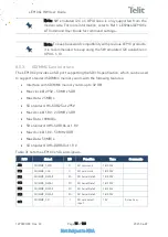
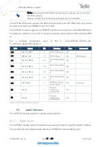
This line of transmission must meet the following requirements:
Item
Value
Characteristic impedance
50 Ohm
Max attenuation
0.3 dB
Avoid coupling with other signals.
Cold End (Ground Plane) of the antenna must be equipotential to the LE910Cx ground pads.
Table 24: Antenna Line on PCB Requirements
Furthermore, if the device is developed for the US and/or Canada market, it must comply
with the FCC and/or IC requirements.
This device is to be used only for mobile and fixed application.
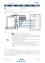
Note:
It is recommended to add PI matching network near the GPS
connector on the application board in case that RF matching is
needed.


