14
WARNING
: Make sure that the front of the antenna is pointed away from any humans or
animals while power is applied! A safe distance is approximately 10 inches or more. The rear
side of the CPE is always safe.
The PoE injector box may be placed on the floor or mounted anywhere near the computer, hub,
switch or router.
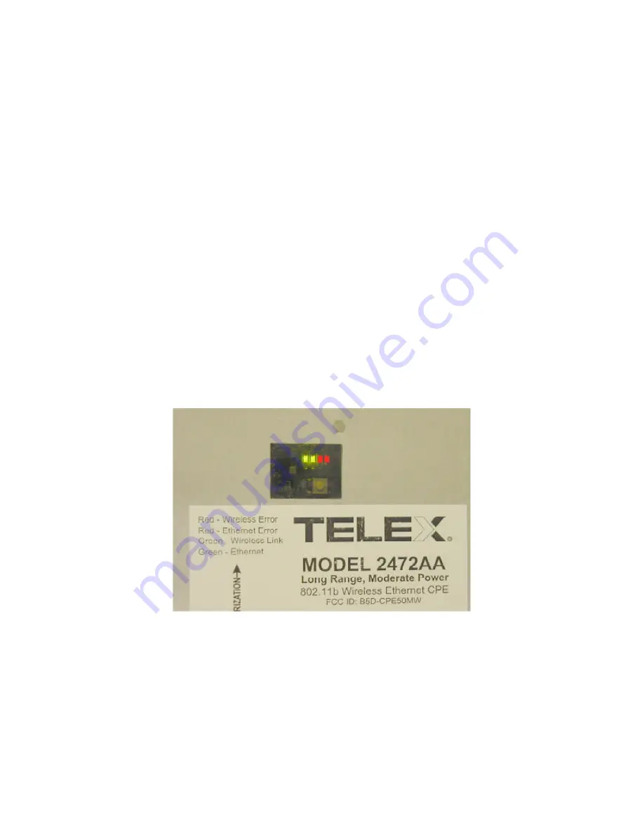
There are 4 LED’s visible from the rear side of the wireless CPE. These can be seen through the
small window in the access panel. When powered-up, the first green LED will be lit ONLY if the
PoE box is connected to an active Ethernet port. If it does not light, then check that all cables are
plugged into the PoE box and the power strip is turned on (if used). If power is supplied and the
cable is plugged into an active Ethernet card, hub, switch or router and the first green LED is not
lit, then move the switch on the PCB inside the CPE to the other position. If this LED is still not
lit, then check the wiring of the RJ45 plugs on the exterior CAT-5 cable. Also check to make
sure that the computer, hub, switch or router is turned on. This green LED will fast blink when
passing Ethernet traffic. The second green LED will light when a connection or association has
been established to a wireless access point and will blink when passing wireless traffic.
The first red LED (3
rd
LED in line) indicates an Ethernet collision. The second red LED (4
th
LED in line) indicates a WLAN error. This LED will light if an access point goes down or is
unavailable after a connection has been made with the CPE. This LED will NOT light if the
SSID is left blank (to use any SSID) and no access points are available. In general, the GREEN
LED’s indicate normal operating conditions and the RED LED’s indicate errors.


