background image


phone: (215) 947-2500        fax: (215) 947-7464       e-mail:[email protected]       web site: www.televac.com


8/15 

8


CHAPTER 7


CHAPTER 8


Maintenance 


No  maintenance  is  required  beyond  periodic  replacement  of  a  contaminated  sensor.  To  replace  the 

sensor, remove the Philips head screw in the center of the instrument, then gently rock and pull off the 

electronic  assembly.  Replace  the  old  sensor  with  a  new  one,  remount  the  electronics  and  replace  the 

Phillips head screw. 

DO NOT OVER TIGHTEN THE SCREW! 

Adjust the “ATM” screw for the proper 

reading when the vacuum system is vented.


Calibration 


All instrumentation is calibrated at the factory. No further calibration at the customer’s facility should be 

required, unless the gauge tube is replaced. In this instance the “ATM” adjustment should be done. No re-

adjustment of the zero should be required unless it has been changed. 


For a reliable recalibration at a later date, it is necessary to have a reference standard vacuum system 

whose pressure is known to be accurate. For such a calibration, the instrument, sensor tube and cable 

should be returned to the factory for re-certification. However, if the vacuum calibration verification must 

be done at the customer’s facility, a knowledgeable electronics technician  trained in vacuum calibration 

should operate equipment of certifiable accuracy. 


Troubleshooting 


1. If display consistently displays “HI”, the atmosphere adjustment may be incorrect or there may be a  

    broken filament in the sensor. If a broken filament is suspected, check for continuity between pins # 4 &   

    # 8 and # 2 & # 6 on the sensor. 


2. If the display constantly reads “LO”, the sensor may have become inoperative. Check for correct  

reassembly after bake out. 


NOTE: If, after doing some or all of the above, the units are still inoperative, return to the factory for 

repair. 


CHAPTER 6


TELEVAC


Содержание MP4AR Series

Страница 1: ...INSTRUCTION MANUAL MP4AR Remote Convection Gauge Range 1 x 10 3 Torr to 1 x 10 3 Torr TELEVAC A DIVISION OF THE FREDERICKS COMPANY 2400 PHILMONT AVE HUNTINGDONVALLEY PA 19006 ...

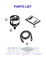
Страница 2: ...TEM DESCRIPTION 1 1 4AR Remote Convection Electronics 2 1 Cable specified at ordering 3 1 Instruction Manual 4 1 Sensor 1 2 4 3 phone 215 947 2500 fax 215 947 7464 e mail sales televac com web site www televac com 8 15 ...

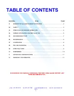
Страница 3: ...NT OPERATION 2 02 SAFETY 3 03 PRINCIPLES OF SENSOR OPERATION 4 04 SENSOR OPERATION AND INSTALLATION 5 05 RECORDER OUTPUTS 7 06 MAINTENANCE 8 07 CALIBRATION 8 08 TROUBLESHOOTING 8 09 SPECIFICATIONS 9 10 DIMENSIONS 10 11 UNPACKING AND INSPECTION 11 12 WARRANTY INFORMATION 11 PLEASE READ THIS MANUAL THOROUGHLY BEFORE USING GAUGE REPORT ANY PROBLEMS IMMEDIATELY ...

Страница 4: ...LC chart recorder or data acquisition system The MP4AR series of instruments use the time proven reliable and rugged TELEVAC 4A Sensor which can be changed in seconds These instruments operate from low voltage DC and are easily integrated into the largest process system with a minimal effort Likewise the MP4AR Remote Gauge can be used as a small stand alone vacuum measurement solution Features Wid...

Страница 5: ...y standards of design manufacture and intended use of the instrument Televac disclaims all liability for the customer s failure to comply with these requirements READ Instructions Read all safety and operating instructions before operating the product RETAIN instructions Retain the Safety and Operating Instructions for future reference HEED warnings Adhere to all warnings on the product and in the...

Страница 6: ...ate measurements Sensors are available in stainless steel or nickel plated brass and can withstand 150 psi overpressure Objects and Liquid Entry Never push objects of any kind into this product through openings as they may touch dangerous voltage points or short out parts that could result in a fire or electric shock Be careful not to spill liquid of any kind onto the products Do not substitute pa...

Страница 7: ...rrespond to values given in chapter 5 depending upon chosen output As the pressure drops below 1 Torr the red MICRONS LED lights and the displayed readings now drop from 990 down to zero while the linear output voltage drops correspondingly from 9 90 Volts to zero 7 0 The trip pressure for the setpoint relay can be displayed by pressing the setpoint display button on the front panel of the instrum...

Страница 8: ... Relay normally closed contact 3 24 volt power 4 Power common 5 Log Linear signal output 6 Relay common contact 7 Non linear signal output 8 Signal return 9 Setpoint output CHAPTER 4 cont TELEVAC Setpoint Display Potentiometer Setpoint Adjust Potentiometer LED display Zero Adjustment Potentiometer Pin s LED lights for microns Phillips Head screw Atmosphere Adjustment Potentiometer SET POINT RELAY ...

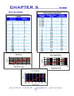
Страница 9: ...on linear Voltage Logarithmic 1 x 10 3 01 0 5 x 10 3 06 70 2 x 10 2 24 1 3 4 x 10 2 45 1 6 6 x 10 2 64 1 78 8 x 10 2 82 1 9 1 98 2 2 1 67 2 3 5 2 99 2 7 8 3 84 2 9 2 5 45 3 3 10 7 32 4 30 7 84 4 48 50 7 93 4 7 80 8 01 4 9 120 8 08 5 08 160 8 19 5 2 180 8 24 5 26 300 8 76 5 48 500 9 57 5 7 760 10 5 88 1000 10 22 6 LINEAR Pressure microns Voltage 1 01 5 05 10 1 20 2 30 3 40 4 50 5 60 6 70 7 80 8 90 ...

Страница 10: ...hould be required unless it has been changed For a reliable recalibration at a later date it is necessary to have a reference standard vacuum system whose pressure is known to be accurate For such a calibration the instrument sensor tube and cable should be returned to the factory for re certification However if the vacuum calibration verification must be done at the customer s facility a knowledg...

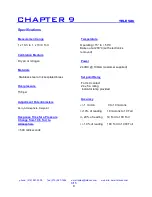
Страница 11: ... Power 24VDC 100mA customer supplied Materials Stainless steel or nickel plated brass Set point Relay Form C contact Overpressure 24 v 5 a rating Indicator lamp provided 150 psi Accuracy Adjustment Potentiometers 1 micron 0 to 10 microns Zero Atmosphere Setpoint 10 of reading 10 microns to 10 Torr Response Time for a Pressure 20 of reading 10 Torr to 100 Torr Change from 10 5 Torr to Atmosphere 10...

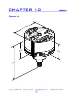
Страница 12: ...phone 215 947 2500 fax 215 947 7464 e mail sales televac com web site www televac com 8 15 10 Dimensions CHAPTER 10 TELEVAC ...

Страница 13: ...authorized to give any guarantee or warranty or make any representation in addition or contrary to those stated herein other than those expressly stated herein there are no other warranties of any kind express or implied and specially excluded but not by way of limitation are the implied warranties of fitness for a particular purpose and merchantability It is understood and agreed the seller s lia...

Отзывы: