background image

Programmable Sweep Instruction Manual 

CONFIGURATION


telemark.com 

32 of 58


Rev 1.0.0 

20 

19 

21 

20 

22 

21 

23 

22 

24 

23 

25 

24 

26 

25 

27 

26 

28 

27 

29 

28 

30 

29 

31 

30 

32 

31 

32 

1 = CLOSED, 0 = OPEN 

* Note in 

“Binary 1=00001” mode, 00001 and 00000 both equal one.


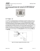
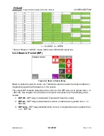
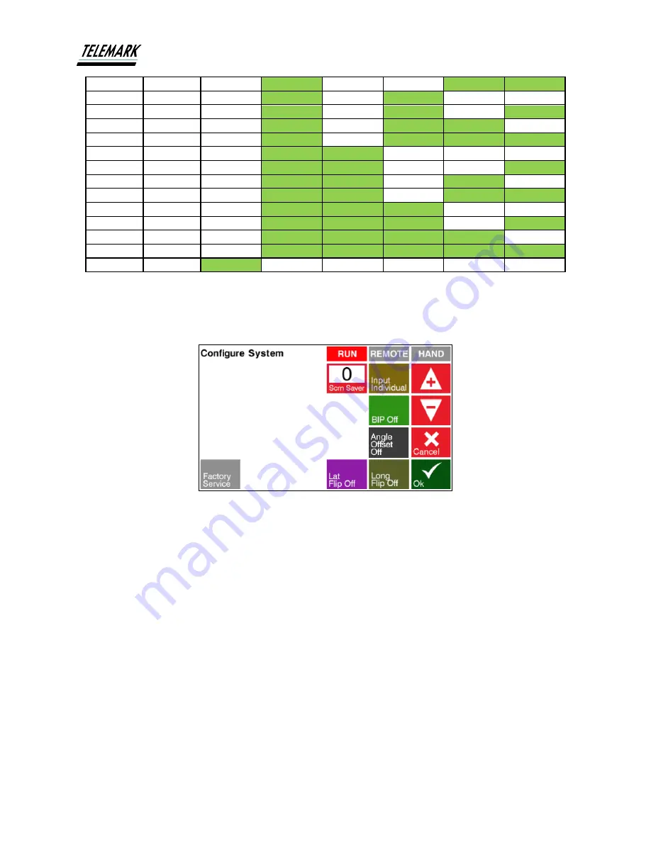
5.2.3 Beam in Pocket (BIP) 


Figure 5-3, Beam in Pocket Setup 

Beam in pocket is used for some non-Telemark e-beam sources that require lateral or 
longitudinal signal that the beam is in the pocket.  

The output BIP contacts close when the current on the BIP axis coil is greater than + or 
- 500 mA. See chapter 3 for the 25 pin connector connections for the following three 
modes: 

1. 

BIP Off


 BIP relay not activated (Telemark E-beam Sources) 

2. 

BIP Lat


 BIP relay activated when current on lateral axis is greater than + or - 

500 mA.  

3. 

BIP Long


 BIP relay activated when current on longitudinal axis is greater than 

+ or - 500 mA.  

Содержание PROGRAMMABLE SWEEP

Страница 1: ...ve Current interface and software options might be different Contact manufacturer for current manual release if the software interface or functions are different from this manual or download the curre...

Страница 2: ...General Data 11 2 1 1 Mechanical Data 11 2 1 2 Ambience 12 2 1 3 Use and Operating Modes 12 2 1 4 Standards 12 2 2 Mains Connection 13 2 3 Pack List 13 2 4 Specifications 14 2 5 Features 15 2 6 Inter...

Страница 3: ...4 2 1 Four way and OK Momentary switch 28 4 2 2 Joystick 29 5 CONFIGURATION 30 5 1 Unlocking 30 5 2 Configure System 31 5 2 1 Screen Saver 31 5 2 2 Input 31 5 2 3 Beam in Pocket BIP 32 5 2 4 Angle Off...

Страница 4: ...1 1 Power Up 48 6 1 2 Power Down 48 6 2 Pattern Selection 49 6 3 Move Pattern 49 6 4 Run On Off 50 6 5 Remote On Off 51 7 MAINTENANCE AND SERVICE 53 7 1 Maintenance 53 7 2 Cleaning 53 8 STORAGE AND DI...

Страница 5: ...Reference Code 23 Figure 3 9 Telemark Source Standard Direction Reference 24 Figure 3 10 Typical 8 pin Sweep coil Installation 24 Figure 3 11 Typical 4 Pin Sweep coil Installation 24 Figure 4 1 Front...

Страница 6: ...ct Shape 44 Figure 5 23 Setup Pattern 44 Figure 5 24 Programmable Shape Select 45 Figure 5 25 Shape Configure 45 Figure 5 26 Shape Edit 46 Figure 5 27 Constant Velocity Shown on Oscilloscope 46 Figure...

Страница 7: ...permanent magnet focusing The sweep output drives the latitude and longitude X Y coils of an electron beam source to move the beam spot The device is referred to as Programmable Sweep in the remainder...

Страница 8: ...by the end user of the product 1 3 2 Illustration of Residual Dangers This Operating Manual illustrates safety notes concerning residual dangers as follows Information on preventing any kind of physi...

Страница 9: ...to all other users of the product Pay attention to the following safety notes Figure 1 1 Keep Foreign Material Out of the Programmable Sweep Improper use Improper use can damage the Programmable Sweep...

Страница 10: ...l INTRODUCTION telemark com 10 of 58 Rev 1 0 0 Improper installation and operation data Improper installation and operation data may damage the Programmable Sweep Strictly adhere to the stipulated ins...

Страница 11: ...chanical Data Dimensions 19 inch 483mm rack 2U 3 1 2 89mm high x 9 3 8 238mm deep See Fig 2 1 Net Weight 10 6 lb 4 8 kg Controller Installation 19 Rack standard or Bench Top unit Assembly Connected ou...

Страница 12: ...erface This mode is active by pressing the Remote button on the touchscreen In this mode the only button available on the touchscreen is to return to manual mode 2 1 4 Standards Conformity with the Di...

Страница 13: ...ory II Protection class 1 Connection US appliance connector IEC 320 C14 Fuse Slow Blow 5 A 250 V 5mm x 20mm 2 3 Pack List Part No Quantity Description 122 4003 1 1 Cable Kit Programmable Sweep 135 030...

Страница 14: ...0 A to B 3 ft LP 124 0925 7 1 Connector Kit 25 Pin D Sub F w Intlk loop 376 9010 1 1 Power Cord 2 4 Specifications Electrical Input Supply Voltage 90 to 264 Vac 47 63 Hz 1 phase operation Input Curre...

Страница 15: ...output runs to each of two coils latitude and longitudinal which are placed perpendicularly to each other Their magnetic fields affect the position motion of the electron beam A simple front panel tou...

Страница 16: ...ly 3 Examine the Programmable Sweep for completeness 4 Visually inspect the Programmable Sweep for signs of damage Damaged product Putting a damaged product into operation can be extremely dangerous N...

Страница 17: ...onents required for setting up the sweep for safe operation Electron beam source with an electromagnetic coil in working order Vacuum system 19 inch rack with 115 230VAC 50 60 Hz power to house the co...

Страница 18: ...of the rack If the product is installed in a rack it is likely to lower the protection class of the rack protection from foreign bodies and water e g according to the EN 60204 1 regulations for switc...

Страница 19: ...e chapter 3 4 7 for details B Main power socket IEC C13 see chapter 3 4 3 for details C Remote Control Input Output interface connector Dsub 25 female see chapter 3 4 5 for details D USB connector Typ...

Страница 20: ...operly grounded devices can be extremely dangerous in the event of a fault Use three wire mains or extension cables with protective ground only Plug the mains cable into wall sockets with protective g...

Страница 21: ...PATTERN SELECT BINARY 1 BIT 0 PATTERN SELECT BINARY 2 BIT 1 RETURN PATTERN SELECT BINARY 3 BIT 2 RETURN PATTERN SELECT BINARY 4 BIT 3 RETURN PATTERN SELECT BINARY BIT 4 5 RETURN PATTERN SELECT BINARY...

Страница 22: ...pins 17 and 5 are open the pattern is selected by a Pattern Select pin being closed contact closed When pins 17 and 5 are closed then a pattern is selected by Binary code input on pins 10 11 12 and 13...

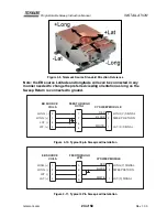
Страница 23: ...ns 1 2 3 of J3 on the Sweep Module as shown The interconnecting wire must be capable of passing a minimum of two amperes The return wire is shared by both longitudinal and lateral coils The sweep volt...

Страница 24: ...orientation as long as the Sweep Return is connected to ground 4 3 1 2 XY SWEEP MODULE LONG SIGNAL Y 3 LONG LAT LAT LONG FEEDTHROUGH OCTAL 1 5 7 EB SOURCE COILS 3 2 BLACK WHITE 1 RED LAT SIGNAL X SWE...

Страница 25: ...5 of 58 Rev 1 0 0 Improper connection In the case of incorrect connection in accordance with Figure 3 8 3 10 and 3 11 there is a danger of damage to the controller 3 5 List of Accessories or Supplies...

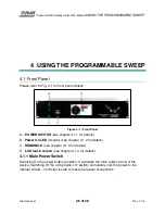
Страница 26: ...see chapter 4 1 1 for details B Power On LED indicator see chapter 4 1 2 for details C HANDHELD see chapter 4 1 3 for details D LCD touch screen see chapter 4 1 4 for details 4 1 1 Main Power Switch...

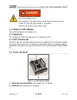
Страница 27: ...chscreen display The screen can be set to turn off using the screen saver setting The Sweep is always operational if the power is on even if the screen is off Touch the screen to wake screen up 4 2 Av...

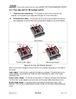
Страница 28: ...e Angle Radius Radius Ok Radius Angle Adjust Figure 4 3 Four way and OK switch Operation When the remote is plugged in it can function in three ways depending on the state of the screen Value Adjust T...

Страница 29: ...oystick directly controls the e beam output position allowing the user to precondition the material manually The Joystick lever controls direction of beam left right controls the lateral direction nea...

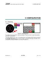
Страница 30: ...reen To configure the sweep first it must be unlocked Press the lock to unlock the sweep and enter the password The default password is 1234 The password can be changed at this time by pressing the Ch...

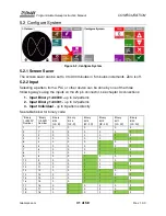
Страница 31: ...1 00000 up to 32 patterns 2 Input Binary 1 00001 up to 32 patterns 3 Input Individual up to 8 patterns directly See table below for binary code Binary 1 00000 Number Binary 1 00001 Number Binary Bit...

Страница 32: ...one 5 2 3 Beam in Pocket BIP Figure 5 3 Beam in Pocket Setup Beam in pocket is used for some non Telemark e beam sources that require lateral or longitudinal signal that the beam is in the pocket The...

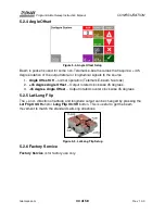
Страница 33: ...Off normal operation Telemark E beam Sources 2 45 degree Angle Offset Output rotated clock wise 45 degrees 3 45 degree Angle Offset Output rotated counter clock wise 45 degrees 5 2 5 Lat Long Flip Th...

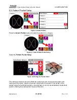
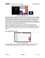
Страница 34: ...Pattern Pocket Setup Select the Pattern Pocket Setup Setup Pocket Pattern 8 Figure 5 8 Setting the Pocket Center First set the pocket center point With the e beam source running at low power and look...

Страница 35: ...ional adjustment use the angle adjustment to move 22 degrees When you are satisfied with all five points then push the Ok button Press Cancel to not save changes to pocket setup Once the center and li...

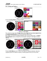
Страница 36: ...e 8 Line Circle Spiral Point or Programmable Shape by touching the desired Shape button Each pattern type stores its setting separately from the other shape types The Reset Current Pattern button will...

Страница 37: ...of the pattern Changing the LCD Tail length 10 1000 makes the display of the pattern more or less visible Note the LCD Tail length has no effect on the actual output to the e beam source 5 7 Profile P...

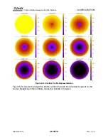
Страница 38: ...CONFIGURATION telemark com 38 of 58 Rev 1 0 0 Figure 5 14 Positive Profile Representations Figure 5 14 shows the larger the profile number the less time the beam spends in the center Negative profile...

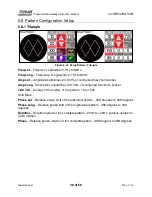
Страница 39: ...ured maximum pocket Amp Long Amplitude Longitudinal 20 100 of configured maximum pocket LDC Tail Display of the history of the pattern 10 to 1000 Shift Menu Phase Lat Relative phase shift of the latit...

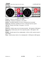
Страница 40: ...Amp Long Amplitude Longitudinal 20 100 of configured maximum pocket LDC Tail Display of the history of the pattern 10 to 1000 Shift Menu Phase Lat Relative phase shift of the latitudinal pattern 359 d...

Страница 41: ...mits of the pocket boundary Figure 5 17 Setup Pattern Figure 8 Freq Frequency 0 1Hz to 80Hz Rotation Rotation speed of the complete pattern 20Hz to 20Hz positive values for CCW rotation Phase Relative...

Страница 42: ...is 0 359 degrees to 359 degrees Amp Amplitude 20 100 of configured maximum pocket LDC Tail Display of the history of the pattern 10 to 1000 Profile 10 0 to 10 0 5 8 5 Circle Figure 5 19 Setup Pattern...

Страница 43: ...100 of configured maximum pocket LDC Tail Display of the history of the pattern 10 to 1000 Profile 10 0 to 10 0 5 8 7 Point Figure 5 21 Setup Pattern Point The point pattern is a fixed point and locat...

Страница 44: ...e is a number in the Prog Shape button then the Prog Shape button can be pressed Figure 5 23 Setup Pattern Freq Frequency 0 1Hz to 80Hz Rotation Rotation speed of the complete pattern positive values...

Страница 45: ...on then it can be edited by pressing Config In the Shape edit mode the circle is gray with a green crosshair to help with designing the shape Figure 5 25 Shape Configure Use Change Shape Name to chang...

Страница 46: ...delete the current step Use Copy to copy shape to another numbered shape 5 9 1 Constant Velocity Constant Dwell Constant Velocity In this mode the sweep moves the beam at a constant velocity irrespec...

Страница 47: ...Programmable Sweep Instruction Manual CONFIGURATION telemark com 47 of 58 Rev 1 0 0 Figure 5 28 Constant Dwell Shown on Oscilloscope...

Страница 48: ...wn below Figure 6 1 Touchscreen Display Then turn on the power supply HV Emission Set the Hi Voltage at the level necessary for the material but set the Emission very low just enough to barely see a b...

Страница 49: ...6 3 Move Pattern Figure 6 3 Pattern Shift Patterns can be shifted in the pocket by pressing the Move Pattern icon Figure 6 4 Move Pattern Joystick connected If the joystick handheld is plugged in Lati...

Страница 50: ...cation will be stored until the Digital Sweep power is turned off In Unlocked mode the new location will be stored in permanent memory till it is reset or changed The Reset button will reset Latitude...

Страница 51: ...t controls the lateral direction near as seen from the EB source emitter far controls the longitudinal direction 6 5 Remote On Off See chapter 3 4 5 for information about the optional Force remote inp...

Страница 52: ...ote then No Pattern Selected is shown and there is no output to the coils Figure 6 9 Remote Pattern Selected If a valid pattern is selected by the remote contact closed see chapter 3 for input descrip...

Страница 53: ...Sweep does not require any special maintenance 7 2 Cleaning For cleaning the outside of the device a slightly moistened cloth will usually do Do not use any aggressive or abrasive cleaning agents Mai...

Страница 54: ...Preferably in an air tight plastic bag with a desiccant 8 3 Disposal The product must be disposed of in accordance with the relevant local regulations for the environmentally safe disposal of systems...

Страница 55: ...Programmable Sweep Instruction Manual STORAGE AND DISPOSAL telemark com 55 of 58 Rev 1 0 0 Figure 8 1 WEEE Symbol...

Страница 56: ...nd Remote mode it turned off The error conditions must be fixed before the Programmable Sweep will be operational Errors may be with the Programmable Sweep the EB source coils or the connection betwee...

Страница 57: ...GS telemark com 57 of 58 Rev 1 0 0 9 2 Interlock Fail Figure 9 1 Interlock Fail When the interlock string is broken a red INTL will show in the upper left corner of the screen the pattern will stop on...

Страница 58: ...teed for any lesser time that such manufacturer warrants its products to Telemark This warranty is valid only for normal use where regular maintenance is performed as instructed This warranty shall no...

Отзывы: