background image

Before you start

4

4

Before you start

product. If the liquid is spilt, it may cause the 
fire, electric shock or breakdown.

•  Do not install it at the place on the strong 

magnetic field or current field. It may cause 
break down. This equipment may be observed 
deterioration of the picture by electromagnetic 
radiation in electromagnetic environment.

•  Fasten the wheel of the product or shelf 

with wheels when installing this product. If it 
moves or is tipped over, it may be damaged.

•  Do not place any fire source such as 

candlelight close to this product or place it on 
this product. If it is tipped over or fallen down, it 
may cause damage or fire.

•  Do not place the unit into closed space 

of TV for better ventilation; it can reduce the 
product lifetime. Keep a space at least 10 cm 
at above, left, and right of the TV.

•  Please place all the signal cords behind of 

rear panel.

•  Do not overexert or touch the panel when 

you convey the product. Do not transfer the 
LED TV up or down display direction.

•  Do not transport it with the power cord 

or the connection cable connected. If you 
move this product with the power cord or the 
connection cable connected, damaged power 
cord, connection cable or connection terminal 
may cause fire, electric shock or breakdown.

•  2 persons or more shall transport the 

device, which is heavier than 18 kg. If you drop 
or tip over the device, it may damage it.

•  The temperature of the product’s body 

becomes a little higher after a long period use. 
This phenomenon indicates that heat exchange 
in normal working mode, thus please do not 
let children or anyone who is sensitive of 
temperature to touch.

All images provided herein are schematic 

drawings of real objects and may differ 
from their real images.

Installation

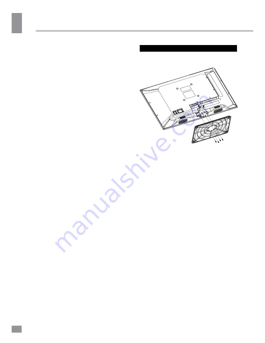
Base instalation

Cover a flat stable surface with a soft cloth. 

Place the TV unit facedown on the cloth. First 
align the base with the holes on the back of the 
unit and fix it with 4 PB4*14mm screws. Then 
match the holes in the stand with the fixing 
pins in the bottom of the base. Fasten with 3 
BB3*8mm screws. 

Wall mounting

•  Unscrew the 4 screws from the stand in 

the back of the unit. Separate the stand from 
the cabinet before wall mounting.

•  For wall mounting the back panel of this 

unit is equipped with 4 screw holes (for 4*8 
screws, 100 mm horizontal spread distance 
x 100 mm vertical spread distance). A 
wall-mount bracket should be used for wall 
mounting (the bracket is not included and 
should be acquired separately). Manufacturer 
is not responsible for improper mounting 
resulting in damage of the unit.

Содержание TF-LED22S6

Страница 1: ...Table of contents 3 LED TV c TF LED22S6 Instruction manual...

Страница 2: ...nel setting Picture setting Sound setting Timer setting Option setting Screen setting USB operation General playback information Operations of file playback General information Troubleshooting Causes...

Страница 3: ...metal part and do not destroy twist pull or roast the power cord Please contact the service center immediately if you found that the core is showed in the air or has been broken Please replace the AC...

Страница 4: ...on cable or connection terminal may cause fire electric shock or breakdown 2 persons or more shall transport the device which is heavier than 18 kg If you drop or tip over the device it may damage it...

Страница 5: ...C adaptor then connect the adaptor to the DC power jack of this unit When using the LED as a computer screen connect the PC to the VGA jack from the monitor by the relevant cable not included This uni...

Страница 6: ...Operation 6 6 Operation Front panel 1 VOL VOL buttons 2 CH CH buttons 3 SOURCE button 4 MENU button 5 POWER STANDBY button Control elements 1 2 3 4 5 2 1 3 4 5 6 7 8 9...

Страница 7: ...nent video input YPbPr Remote controller RC 1 2 3 4 5 6 7 8 9 10 11 12 13 14 15 16 17 18 19 20 21 22 23 24 25 26 27 28 29 30 31 32 33 34 35 1 POWER button 2 Number buttons 3 P MODE button 4 S MODE but...

Страница 8: ...VOL button repeatedly to decrease the volume press VOL button repeatedly to increase the volume Press SLEEP button repeatedly to set the sleep time from 10 to 240 min Press button on the RC to select...

Страница 9: ...lable press this button to return to TV mode When the required page is found its number will be displayed at the top of the screen press this button to return to the teletext mode and browse the page...

Страница 10: ...your favorite channel by pressing FAV button Picture setting PICTURE Picture mode Contrast Brightness Color Tint Sharpness Color temperature Noise reduction Move Menu OK Exit Picture Mode Standard Dyn...

Страница 11: ...tents to play by pressing LEFT RIGHT cursor buttons and ENTER button USB file systems supported FAT16 FAT32 NTFS 2 0 USB version is supported maximum capacity 400 Gb For correct and satisfactory opera...

Страница 12: ...t available for text files and picture will be previewed in the center not available for music and text files Press ENTER button or CAN CEL button to play the selected file While playback press ENTER...

Страница 13: ...ck Press INDEX button to stop playback When playing photo movie and music files you can press REPEAT button to select the repeat play mode Press ROOT button to go to the root menu of the storage When...

Страница 14: ...te interference Local radiation however can create disturbances which visibly affect your picture Proper installations a good aerial are your best safeguards against these disturbances RF INTERFERENCE...

Страница 15: ...oltage range of the adaptor 100 240 V 50 60 Hz Nominal voltage range of the LED TV output voltage of the adaptor 12 V Power consumption of the LED TV 36 W Unit dimensions without stand 503 x 51 3 x 31...

Страница 16: ...16 16 USB 15 16 16 16 18 18 18 19 19 19 20 20 20 20 21 21 22 22 22 23 23 24 24 24 24 25 25 25 25 28 28 28 29 30...

Страница 17: ...17 17 220...

Страница 18: ...18 18 LED 10 18 2...

Страница 19: ...19 19 3 4 8 4 4 8 100...

Страница 20: ...20 20 75 DVD CAMCORDER L R RCA Y Pb Pr VGA VGA VGA HDMI HDMI HDMI 75 Ohm co axis cable TVRF antenna jack Antenna cable connector ST AN DB Y...

Страница 21: ...21 21 1 VOL VOL 2 CH CH 3 SOURCE 4 MENU 5 POWER 1 2 USB 3 HDMI 4 VGA 5 6 7 8 9 YPbPr 1 2 3 4 5 2 1 3 4 5 6 7 8 9...

Страница 22: ...POWER 2 3 P MODE 4 S MODE 5 MENU 6 ENTER 7 EXIT 8 MTS 9 VOL VOL 10 ROOT 11 FAV 12 FAV 13 CANCEL 14 INDEX 15 REVEAL 16 SIZE 17 RED 18 GREEN 19 MUTE 20 21 SLEEP 22 SOURCE 23 INFO 24 CH CH 25 ASPECT 26 R...

Страница 23: ...L VOL SLEEP 10 240 ASPECT 4 3 16 9 1 2 MUTE TV CH CH 0 9 P MODE SMART S INFO FREEZE FAV FAV FAV MTS TV Nicam SOURCE CH CH TV AV SCART YPBPR HDMI PC ENTER MENU TV CH CH ON OFF TEXT HOLD INDEX SIZE REVE...

Страница 24: ...24 24 CANCEL CANCEL MIX 1 MENU 2 VOL 3 ENTER CH 4 CH 5 VOL CH 6 EXIT ENTER MENU EXIT ENTER PAL SECAM NTSC DK BG I ENTER...

Страница 25: ...25 25 FAV NTSC 10 240 USB...

Страница 26: ...26 4 3 16 9 1 2 USB PC c USB USB USB USB ENTER USB ENTER USB USB 2 0 FAT16 FAT32 NTFS 400 USB ASF AVI MKV MPG WMV9 DIVX H263 MPEG 4 MPEGII XVID WMA MP3 DD AC3 576x720 AVI AVI 2 USB 1 1 2 0 USB 500 USB...

Страница 27: ...27 27 USB USB BIN ENTER ENTER CANCEL ENTER CANCEL ENTER ENTER OK OK...

Страница 28: ...28 28 CANCEL INDEX REPEAT ROOT...

Страница 29: ...29 29 VGA...

Страница 30: ...30 30 1 1 2 1 3 1 4 1 5 7 6 1 7 1 8 1...

Страница 31: ...21 5 55 1920 x 1080 16 9 8 PAL SECAM B G DK I NICAM 2 x 3 RCA VGA HDMI 3D 199 USB 1000 II 100 240 50 60 12 36 503 x 51 3 x 315 9 503 1 x 175 8 x 340 3 3 08 3 59 TF LED22S6_IM_01 31...

Отзывы: