


70
-
TBD
©
2007-2020
A
LL RIGHTS RESERVED TO
T
ELE
F
IRE
F
IRE AND
G
AS
D
ETECTORS
L
TD
.
R
EVISION
1.11
F
EBRUARY
2020
Page
16 of 19
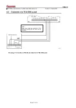
4
Connection to the TeleFire panels
i
Note
24VDC supply to the detector will be provided from 24R input in
TSA-200 /
TSA-240 and TSA-1000 panels, and from 24V input for ADR-712 assembly.
Make sure that the ADR-712 assembly is of software version 6 and higher.
Do not use ADR-812A assembly to connect to addressable panels
.
Usually smoke that goes up starts spreading sideways at a certain distance below the
ceiling, because of a layer of hot air that is found next to the ceiling. Therefore the
detector has to be installed on the building wall, at least 50-cm and no more than 1-m
below the ceiling, to meet the requirements of NFPA 72/ UL 268 and Israeli Standard IS
1220-3, 2014 revision.
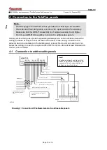
4.1 Connection to addressable panels
Drawing 1: Connection of FireBeam detector to addressable panels
Note!
In software version 6 and higher of the
ADR-712, TBR-5100 reset circuit is not
necessary. Do not use assemblies of
software revision 5 and lower.
Zone
2
Zone
1
24V supply to zones
24VR supply
Fire beam detector
Continued 24V line to the next device
Communication line to the next device
Communication line to devices
from the panel or previous
device
Connect 5.1k end-of-line resistor to
each zone
Continued 24V line to the next device
Shielding


