70
-
TBD
©
2007-2020
A
LL RIGHTS RESERVED TO
T
ELE
F
IRE
F
IRE AND
G
AS
D
ETECTORS
L
TD
.
R
EVISION
1.11
F
EBRUARY
2020
Page
13 of 19
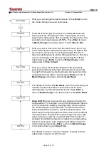
Use the right and left arrows to turn on or off the green
flashing LED lamp on the controller.
When using several beam detectors directed one against the
other, an error in data reading can occur. By properly setting
each beam and its phase, you can solve this problem. Use the
right and left arrows to set a different phase pattern for each
beam (conduct samplings of the output beam). You can
choose from 0 (default) to 6 (press
Enter
to return to
Mode
Change
or the down arrow to go to Hysteresis.
A change in the hysteresis changes the hysteresis in the
transition between Fire mode back to Normal Mode. For
example, the beam default is 15%, such that if the beam is set
to alarm mode at 65% (threshold of 35%), the beam intensity
has to reach 15-80% before it returns to normal state. This
operation prevents fluctuations in the reflected signal causing
the beam to go in and out of alarm mode. It can be adjusted
between 1% and 40% using the left and right arrows (press
Enter
to return to
Mode Change
or down to go to
Compensation fire/ fault
).
Press
Enter
to go to
Beam Maintenance
.
This screen displays the beam compensation due to
construction dust that goes up to the beam head and reflector.
Always look at this value as part of the ongoing maintenance.
If a value higher than 50% is displayed, the beam head and
reflector have to be cleaned (after cleaning, activate auto
alignment to reset the beam).
A negative value can be displayed, when the detector is
installed in a dusty environment. To reset, press
Auto
alignment
(press
Enter
to return to
Beam Maintenance
or
the down arrow to go to
Event Counts
).


