


Telefire
ADR-3000 – System Introduction
Revision 1.10 4 November 2004
List of Figures
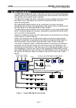
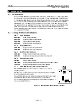
Figure 1
Typical ADR-3000 fire alarm system ............................................................................. 1
Figure 2
Internal module location in the ADR-3000 cabinet ........................................................ 3
Figure 3
ADR-3001 Main board...................................................................................................3
Figure 4
Line cards ...................................................................................................................... 4
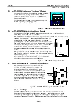
Figure 5
ADR-3003 Keyboard and display .................................................................................. 5
Figure 6
ADR-4004 Power supply module .................................................................................. 5
Figure 7
LON-3000 Networking communication module............................................................. 5
Figure 8
Bus topology .................................................................................................................. 6
Figure 9
Ring topology................................................................................................................. 6
Figure 10 Mixed (free) topology..................................................................................................... 6
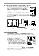
Figure 11 GIM-232 Module ............................................................................................................ 7
Figure 12 GIM-232 Connection...................................................................................................... 7
Figure 13 MCID-34 Modem module .............................................................................................. 7
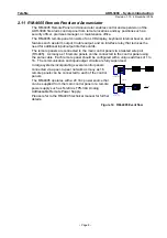
Figure 14 RM-4005 Event flow ...................................................................................................... 8
Figure 15 ADR-805 Flow Switch Interface Module...................................................................... 12
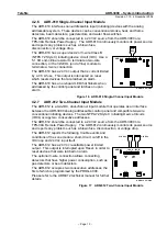
Figure 16 ADR-810 Single-Channel Input Module ...................................................................... 13
Figure 17 ADR-812 Two-Channel Input Module.......................................................................... 13
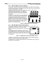
Figure 18 ADR-818 Eight-Channel Input Module ........................................................................ 14
Figure 19 ADR-820 Single-Channel Output Module Interface .................................................... 14
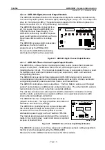
Figure 20 ADR-828 Eight-Channel Output Module ..................................................................... 15
Figure 21 ADR-823 Three-Channel Input/Output Module ........................................................... 15
Figure 22 ADR-833 Extinguishing Control Unit ........................................................................... 16
Figure 23 LI-3000 Line Isolation Module ..................................................................................... 16
Figure 24 EPI-3000 Electromagnetic and Surge Protection Interface Module............................ 18
Figure 25 Connecting an evacuation system via General Output ............................................... 19
Figure 26 Connecting an evacuation system via an Addressable Output................................... 20
Figure 27 Connecting secondary units ........................................................................................ 20
Figure 28 Multi-amplifier system in a multi-storey building.......................................................... 21
— III —


