


301/303/305/306/307 Flowmeters and Controllers Instruction Manual
EAR99 Technology Subject to Restrictions Contained on the Cover Page
Page 18 of 32
2.6.4. Vertical Mounting
It is not recommended to mount the
instrument vertically if high pressure or high
density gas is being measured.
If the instrument is not mounted in a level
position and is operating at high pressure or
with high density gases, the increased gas
density will cause convection to flow through
the sensor tube. This natural convection flow
will be proportional to the square of the gas
density and therefore to system pressure. This
will be seen as a shift in the zero flow output
that changes as the system pressure changes.
Heavier gases will have more of an effect than
light gases.
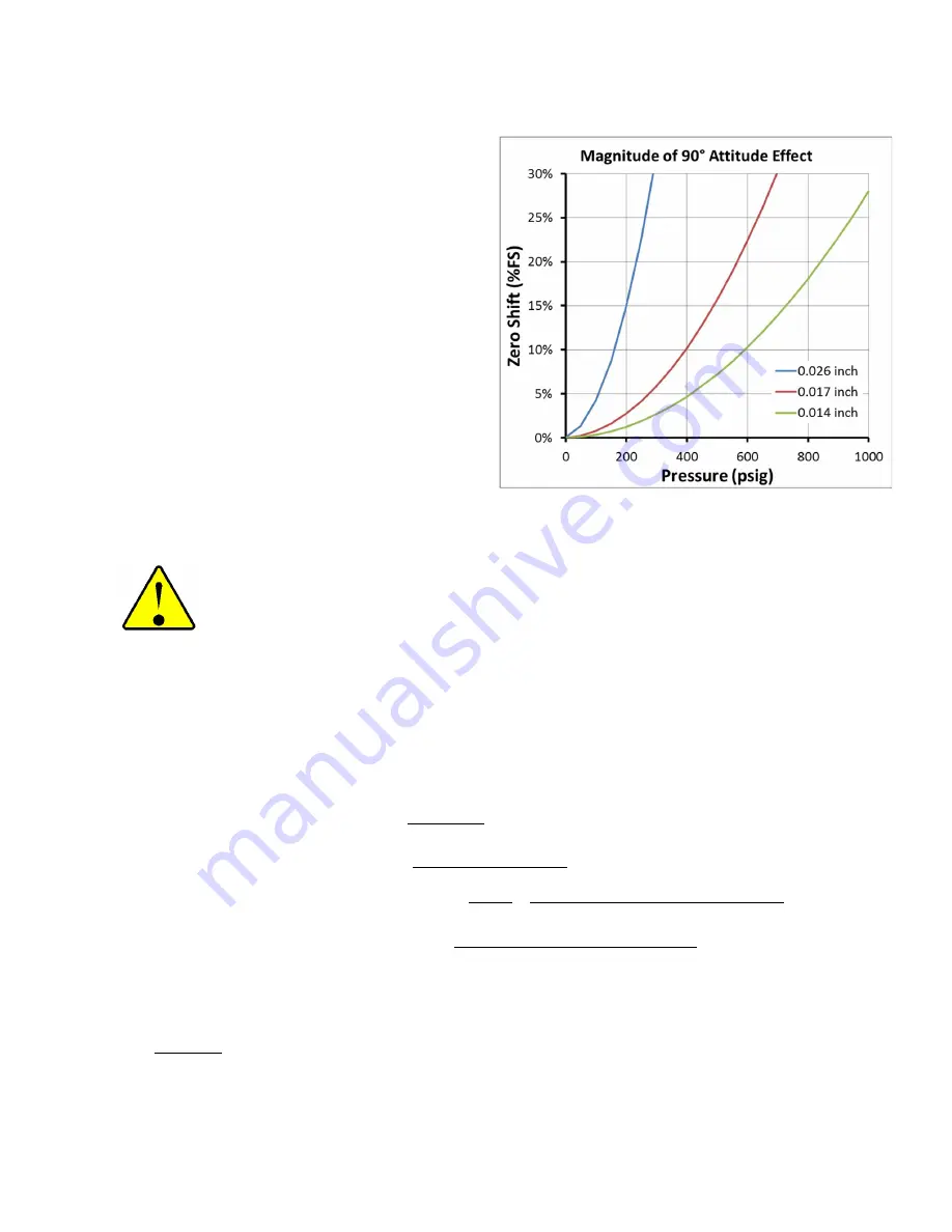
If the error exceeds 20-30% (of full scale), the
zero circuit installed in the instruments may
no longer be able to be adjusted to
compensate for the error.
If the instrument is measuring light gases or low pressure, the change in the zero due to natural
convection will be minimal. Larger shifts could be zeroed out with the zero pot as long as the upstream
pressure is stable. A chart is shown here for nitrogen/air versus pressure.
CAUTION:
The HFM-306 does not have a high pressure option and is only rated for a 300 psig
max working pressure.
2.6.5. Gas Blending
Gas blending is achieved by using the output of one flow controller as the control signal (setpoint or
scaled setpoint) to a second flow controller (maintaining a fixed ratio of one gas to another).
Multichannel Hastings Power Supplies allow users to configure this option, but other devices can be used,
provided they can scale and feed the output signal of one controller to another. The following formulas
are useful (Two controllers, unit A and unit B, where FS = Full Scale):
𝐴 𝐹𝑙𝑜𝑤 = (𝐴 𝐹𝑆 𝐹𝑙𝑜𝑤)
𝐴 𝑂𝑢𝑡𝑝𝑢𝑡
𝐴 𝐹𝑆 𝑂𝑢𝑡𝑝𝑢𝑡
,
𝑙𝑒𝑡 𝐵 𝑆𝑒𝑡𝑝𝑜𝑖𝑛𝑡 = 𝐴 𝑂𝑢𝑡𝑝𝑢𝑡 × 𝑆𝑐𝑎𝑙𝑒 𝐹𝑎𝑐𝑡𝑜𝑟
𝐵 𝐹𝑙𝑜𝑤 = (𝐵 𝐹𝑆 𝐹𝑙𝑜𝑤)
𝐴 𝑂𝑢𝑡𝑝𝑢𝑡 × 𝑆𝑐𝑎𝑙𝑒 𝐹𝑎𝑐𝑡𝑜𝑟
𝐵 𝐹𝑆 𝑂𝑢𝑡𝑝𝑢𝑡
,
𝐹𝑙𝑜𝑤 𝑅𝑎𝑡𝑖𝑜 =
𝐵 𝐹𝑙𝑜𝑤
𝐴 𝐹𝑙𝑜𝑤
=
(𝑆𝑐𝑎𝑙𝑒 𝐹𝑎𝑐𝑡𝑜𝑟)(𝐵 𝐹𝑆 𝐹𝑙𝑜𝑤)(𝐴 𝐹𝑆 𝑂𝑢𝑡𝑝𝑢𝑡)
(𝐴 𝐹𝑆 𝐹𝑙𝑜𝑤)(𝐵 𝐹𝑆 𝑂𝑢𝑡𝑝𝑢𝑡)
𝑆𝑐𝑎𝑙𝑒 𝐹𝑎𝑐𝑡𝑜𝑟 =
(𝐹𝑙𝑜𝑤 𝑅𝑎𝑡𝑖𝑜)(𝐴 𝐹𝑆 𝐹𝑙𝑜𝑤)(𝐵 𝐹𝑆 𝑂𝑢𝑡𝑝𝑢𝑡)
(𝐵 𝐹𝑆 𝐹𝑙𝑜𝑤)(𝐴 𝐹𝑆 𝑂𝑢𝑡𝑝𝑢𝑡)
In most cases the analog full scale output terms are the same so those two terms cancel out. The flow
ratio is usually known, so the only challenge is finding the value of the scale factor between the output
of A to generate the setpoint of B.
EXAMPLE: Controller A is a 100 SLM Nitrogen 5V controller. Controller B is a 10 SLM CO
2
5V controller.
What needs to happen to maintain CO
2
at 5% of the Nitrogen flow rate? See solution on following page.