4 Operation
Model 7300A
4-14
Teledyne Analytical Instruments
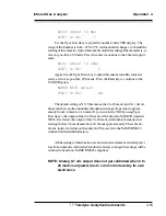
How the offset value is selected:
To find out what the offset value should be, the intended zero calibration
gas and the mix of the process background gas must be procured. This of course
assumes that the zero gas and the process background gas are very different and
that an offset will occur.
1. Let the intended zero calibration gas flow through the 7300A sample cell
(this assumes that you have started up your system as recommended by the
manual or technical personnel) and do a zero on the instrument. Leave the offset
set to zero value.
2. At the end of the zero function, make sure the analyzer reads zero.
3. Span the analyzer
4. Flow the process background gas mix through the 7300A sample cell on
the Analyze mode. Wait for the reading to become stable. Write the reading
down. Change the sign of the reading: This is the offset to be entered.
5. Do a manual run to check the analyzer operation. Reintroduce the zero
calibration gas. Enter the zero Offset value as explained above.
6. Check that the instrument reads the entered offset.
7. Reintroduce the process background gas mix to the 7300A sample cell
in the Analyze mode. It should read close to zero once the reading is stable (+/-
1% error of full scale).
Spanning the 7300A:
Since the instrument might be spanned with a background gas the same
as the zero calibration gas, the span value to be entered should be the span
concentration plus the offset value (if the offset value has a minus sign then
algebraically it becomes a subtraction).
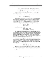
4.3.11 CAL-OUT Function
Selecting the CAL-OUT function in menu makes possible to calibrate the
output of the 4 to 20 madc. In hardware terms, this function calibrates the Digital
to Analog converter that feeds a signal to the 4 to 20 madc E/I converter.
Calibrating the 4 to 20 madc output should be part of routine maintenance.
To calibrate the 4 to 20 madc output, a calibrated multi-meter configured
as an ammeter has to be connected to the analyzer to monitor the output. When
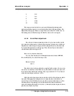
ready, enter the CAL-OUT function. The following screen will be shown on the
VFD display:
Содержание 7300A
Страница 4: ...iv Model 7300A Teledyne Analytical Instruments ...
Страница 12: ...1 4 1 Introduction Model 7300A Teledyne Analytical Instruments ...
Страница 26: ...2 Installation Model 7300A 2 14 Teledyne Analytical Instruments ...
Страница 36: ...3 Start up and Theory of Operation Model 7300A 3 10 Teledyne Analytical Instruments ...
Страница 80: ...5 Maintenance Model 7300A 5 10 Teledyne Analytical Instruments ...


