background image

Searching the satellite

During the seeking stage, the green LED by the name of the satellite blinks fast, while the
message ON appears on the display (4) followed by an animated bar which indicates the
rotation of the antenna. The antenna will stop moving as soon as it finds the satellite; in this
case the message SAT will be brought to the display and the green signal light will remain
always on. At this point the satellite receiver and the desired TV program can be turned on.

The position of the antenna will automatically be saved after first satellite tracking
operation: this speeds up tracking when the system is switched back on after parking
the antenna.

Automatic Parking of antenna via the Control Panel (OFF indicator off)

Should you decide to park (stow) the antenna by pressing key (2), the antenna starts to be
lowered and the word OFF appears on the Display. Once the antenna has been completely
closed the word OFF disappears and only the Power LED remains on.

Turning off the TeleSat S

If you wish to turn off the TeleSat S, press the ON/OFF button (3) and make sure that all
signal lights are off. In this case the antenna remains in the position it was before turning off.
Proper connection of the green safety cable ensures that the antenna is closed as long as
the vehicle moves.

Error code display

In the event of faults or malfunctions, the Control Panel shows the corresponding Error Code
on the display:

ER1


No satellite found. It is necessary to check that the TeleSat S system is not
obstructed SOUTH of the satellite.

ER2


The elevation motor is locked. Make sure that no foreign matters hinder regular
 movement

ER3


The rotation motor is locked. Make sure that no foreign matters hinder regular movement

ER9

During the switch-on stage a fault occurred in the driving motor. Make sure that no
foreign matters hinder regular movement.

ON/OFF

button (3)

Antenna parking

button (2)

Message display

(4)

14

Содержание TeleSat S65

Страница 1: ...Installation guide and user manual GB...

Страница 2: ......

Страница 3: ...out by personnel not authorised by Teleco e Normal part wear f Expenses incurred for spare parts transport between the Customer s and the service centre g Damages that may occur during transport the C...

Страница 4: ...ation 10 Tips on the best use of TeleSat S 12 Operation of TeleSat S 13 Troubleshooting 15 Technical specifications 15 Spare Parts Table 16 Recycling with a view to reducing disposal of waste electric...

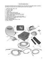
Страница 5: ...tor driven unit 2 65 85 cm dish 3 Universal LNB 4 Control unit 5 Wall mounted control panel 6 Motor connecting cable extension 7 Coaxial cable extension for antenna signal 8 Power Supply Cable 9 Contr...

Страница 6: ...as follows 1 Temporarily connect the Control unit to the driving unit through the grey motor cable 2 Connect the Control panel to the Control unit through the RJ45 cable 3 Power the Control unit using...

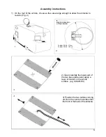
Страница 7: ...IKAFLEX 3 Position the two cables coming out from the centre towards either the front or the back of the antenna Assembly instructions 1 On the roof of the vehicle choose a free area large enough to a...

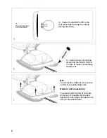
Страница 8: ...Apply a layer of silicone all around the BASE PLATE in order to make it completely waterproof N B To service the Outdoor Unit screw out the four self locking nuts Outdoor unit reassembly To ensure ti...

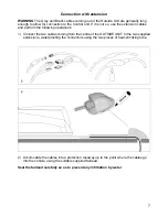
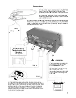
Страница 9: ...onnection with extension WARNING The Grey and Black cables coming out of the Outside Unit are generally long enough to allow for connection to the Control unit If it is not so use the extension cables...

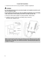
Страница 10: ...onality and render the warranty null and void 2 Place the Control panel comando in an easily accessible visible position 3 Install the connection cables Grey and Black until you reach the OUTSIDE UNIT...

Страница 11: ...n this way whenever the motor is started this cable receives a positive 12 Vdc voltage which will automatically lower the antenna and lock all functions of the Control Unit simultaneously 1 Connect th...

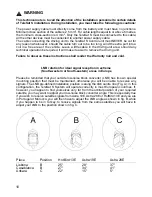
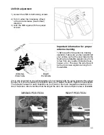
Страница 12: ...peration be required it will make it easier to remove the driving unit Failure to observe these instructions shall render the Warranty null and void LNB rotation for ideal signal reception in extreme...

Страница 13: ...llites do not transmit with the same intensity throughout Europe so if you are outside the reception area your TeleSat S search might be unsuccessful The reception areas for each Satellite can be foun...

Страница 14: ...e sure that your batteries are always sufficiently charged since if the voltage falls below 10 Volts the TeleSat S electronic safety circuit will prevent the antenna from rising 5 Should you use 12 Vo...

Страница 15: ...ressing the button all signal lights will go on to allow you to check the proper operation of the board After this step the message ON will appear on the display 4 the red power supply indicator 6 wil...

Страница 16: ...n the Display Once the antenna has been completely closed the word OFF disappears and only the Power LED remains on Turning off the TeleSat S If you wish to turn off the TeleSat S press the ON OFF but...

Страница 17: ...services you wish to receive are really available on the required satellite If the Control panel does not turn on when you press the ON OFF button check the following a Is the engine of your vehicle r...

Страница 18: ...16...

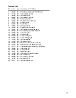
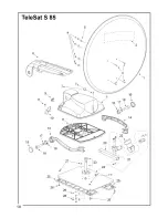
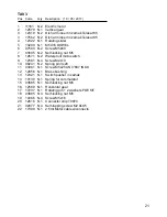
Страница 19: ...2 N 3 Self locking rivet SR 3580 W 13 12857 N 1 Lnb arm right 14 12858 N 1 Lnb arm left 15 12862 N 1 Lnb bushing left 16 12861 N 1 Lnb bushing right 17 13503 N 2 Spring washer 18 13434 N 2 Screw M10X4...

Страница 20: ...18...

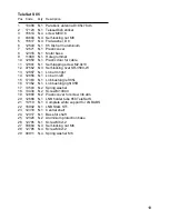
Страница 21: ...locking rivet SR 3580 W 13 12857 N 1 Lnb arm right 14 12858 N 1 Lnb arm left 15 17363 N 1 Lnb bushing left 85L 16 17362 N 1 Lnb bushing right 85R 17 13503 N 2 Spring washer 18 13434 N 2 Screw M10X40 1...

Страница 22: ...20...

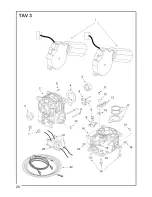
Страница 23: ...Waterproof microswitch 9 12581 N 4 Screw M2x10 10 09241 N 2 Spring pin 3x20 11 03081 N 1 Screw M5x25 UNI 7687 INOX 12 12856 N 1 Brass bushing 13 12321 N 1 Switch pusher in zamak 14 13130 N 1 Spring f...

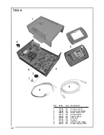
Страница 24: ...N 1 Control unit lid 2 15054 N 1 Control unit bottom 3 09835 N 4 Black rubber foot 4 15112 N 1 Control panel 5 16556 N 1 T0215 board 6 02203 N 1 4A Fuse 7 01458 N 4 Support 8 11742 N 1 PATCH UTP Cable...

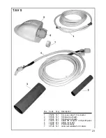
Страница 25: ...1 3 m coax cable F F connector 2 03598 N 1 Shrink wrap sheath 3 03597 N 1 Shrink wrap sheath 4 13018 N 1 Cable 3M 2 8pin F 2 8pin M poles 5 17159 N 1 Cable cover abs 6 16984 N 1 PG32 assembly 7 07126...

Страница 26: ...ificate conform to the following norms EN 60065 2002 EN 55013 2001 A1 2003 EN 61000 3 2 2000 A2 2005 EN 61000 3 3 1995 A1 2001 A2 2005 EN 55020 2002 A2 2005 according to the terms of the European dire...

Страница 27: ......

Страница 28: ...19 05 2017...

Отзывы: