Operating Basics
12
P5205 Instruction Manual
Both ranges are rated for the maximum input limits, but you can
obtain a useful measurement only if the voltage you apply is within
the specified limits of the operating range.
Overrange Detection
Differential voltage outside the operating range will overdrive the
circuitry of the probe and distort the output signal. When this
differential overrange occurs, the probe detects the condition and
lights the overrange indicator. With the Audible Overrange ON, the
probe will also emit an audible alarm.
Common-mode voltage greater than 1,000 V
RMS
can distort the
output signal, but the probe will not indicate an overrange condition.
Common-Mode Rejection
The common-mode rejection ratio (CMRR) is the specified ability of
P5205 probe to reject signals that are common to both inputs. More
precisely, CMRR is the ratio of the differential gain to the common-
mode gain. The higher the ratio, the greater the ability of probe to
reject common-mode signals. For exact specifications, see pages 15
and 17.
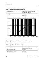
Common mode rejection decreases as the input frequency increases.
Figure 5 on page 18 is a plot of typical CMRR of the probe versus
input frequency. For example, if you apply a 60 Hz line voltage of
500 V
P-P
to both input leads of the probe, the probe rejects the signal
by 80 dB (typical) and the signal appears as only a 50 mV
P-P
signal
on the oscilloscope screen.
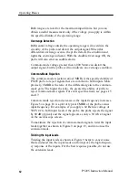
To maximize the rejection of common-mode signals, twist the input
leads together as shown in Figure 3 on page 13, and do not use the
extension leads.
Twisting the Input Leads
Twisting the input leads as shown in Figure 3 helps to cancel noise
that is induced into the input leads and to improve the high-frequen-
cy response of the inputs. For the best response possible, do not use
the extension leads.
Содержание P5205
Страница 1: ...Instruction Manual P5205 High Voltage Differential Probe 070 9472 01 www tektronix com ...
Страница 4: ......
Страница 14: ...Getting Started 2 P5205 Instruction Manual ON Figure 1 High Voltage Differential Probe ...
Страница 20: ...Getting Started 8 P5205 Instruction Manual ...
Страница 38: ...Maintenance 26 P5205 Instruction Manual ...
Страница 40: ......
Страница 49: ...Replaceable Parts P5205 Instruction Manual 35 1 2 3 4 5 6 Figure 14 P5205 Probe and replaceable accessories ...
Страница 54: ...Replaceable Parts 40 P5205 Instruction Manual ...


