background image

P5205 Instruction Manual

9

Operating Basics

To help you use the High Voltage Differential Probe safely and
effectively, this section provides important information about safety
limits, operating characteristics, and probing techniques.

WARNING.

Due to the inherent hazards associated with taking

high

-

voltage measurements, the product is intended for use by

qualified personnel who have had the training to make these types of
measurements. Read and follow the precautions specified in this
manual.

Before you make any oscilloscope measurement, observe all safety
precautions described in the user and service manuals for the
equipment you are working on. Some general rules about using and
servicing electrical equipment are worth repeating here.

H

Observe the safety instruction symbols for the equipment you are
working on.

H

Consult the instruction or service manuals for the equipment you
are working on.

H

Don’t operate or service an electrical device in an explosive
atmosphere.

H

Avoid personal injury by never touching exposed connections or
components in the circuit-under-test when the power is on.

Operating the Probe Safely

Before connecting the inputs of the probe to a circuit, read the safety
information in this section, and attach the appropriate accessories to
the input connectors of the probe.

Содержание P5205

Страница 1: ...Instruction Manual P5205 High Voltage Differential Probe 070 9472 01 www tektronix com ...

Страница 2: ...d pending Information in this publication supercedes that in all previously published material Specifications and price change privileges reserved Tektronix Inc P O Box 500 Beaverton OR 97077 TEKTRONIX TEK and TEKPROBE are registered trademarks of Tektronix Inc TekProbe is a registered trademark of Tektronix Inc ...

Страница 3: ... charges for products returned to any other locations This warranty shall not apply to any defect failure or damage caused by improper use or improper or inadequate maintenance and care Tektronix shall not be obligated to furnish service under this warranty a to repair damage resulting from attempts by personnel other than Tektronix representatives to install repair or service the product b to rep...

Страница 4: ......

Страница 5: ...1 Operating Limits 11 Overrange Detection 12 Common Mode Rejection 12 Twisting the Input Leads 12 Extension Leads 13 Probe Loading 14 Specifications 15 Warranted Characteristics 15 Typical Characteristics 17 Nominal Characteristics 19 Maintenance 21 Cleaning 21 Servicing the Compensation Box 21 Replacing TEKPROBE Interface Pins 21 Removing and Replacing the TEKPROBE Interface Collar 23 Removing th...

Страница 6: ...of Contents ii P5205 Instruction Manual Bandwidth 31 DC CMRR 32 Replaceable Parts 33 Parts Ordering Information 33 Using the Replaceable Parts List 33 Abbreviations 34 Mfr Code to Manufacturer Cross Index 34 ...

Страница 7: ...enuation 18 Figure 6 Input impedance vs frequency 19 Figure 7 Replacing TEKPROBE interface pins 22 Figure 8 Replacing the TEKPROBE collar 23 Figure 9 Removing the compensation box covers 24 Figure 10 Replacing the compensation box cover 25 Figure 11 BNC male to dual binding post adapter 28 Figure 12 Removing plastic covers from binding posts 29 Figure 13 Slide probe leads onto the binding posts 30...

Страница 8: ...arranted Electrical Characteristics 15 Table 3 Certifications and Compliances 16 Table 4 Typical Electrical Characteristics 17 Table 5 Typical Mechanical Characteristics 18 Table 6 Nominal Electrical Characteristics 19 Table 7 List of Equipment Required 27 Table 8 Parts List Column Descriptions 34 ...

Страница 9: ...e measurement instrument before connecting the probe to the circuit under test Disconnect the probe input and the probe ground from the circuit under test before disconnecting the probe from the measure ment instrument Ground the Product This product is indirectly grounded through the grounding conductor of the mainframe power cord To avoid electric shock the grounding conductor must be connected ...

Страница 10: ...tions or practices that could result in injury or loss of life CAUTION Caution statements identify conditions or practices that could result in damage to this product or other property Terms on the Product These terms may appear on the product DANGER indicates an injury hazard immediately accessible as you read the marking WARNING indicates an injury hazard not immediately accessible as you read t...

Страница 11: ... Do not perform internal service or adjustments of this product unless another person capable of rendering first aid and resuscitation is present Use Care When Servicing with Power On Dangerous voltages or currents may exist in this product Disconnect power remove battery if applicable and disconnect test leads before removing protective panels soldering or replacing components To avoid electric s...

Страница 12: ...800 833 9200 select option 1 Service support 1 800 833 9200 select option 2 Technical support Email techsupport tektronix com 1 800 833 9200 select option 3 1 503 627 2400 6 00 a m 5 00 p m Pacific time This phone number is toll free in North America After office hours please leave a voice mail message Outside North America contact a Tektronix sales office or distributor see the Tektronix web site...

Страница 13: ...l buttons are isolated and double insulated This protection extends up to the full input rating of the probe The accessories supplied with the probe meet the same safety standards as the probe You may use other accessories if they are approved for the maximum voltage present in your application and have the same style and size connectors The P5205 probe allows clear and accurate measurements of hi...

Страница 14: ...Getting Started 2 P5205 Instruction Manual ON Figure 1 High Voltage Differential Probe ...

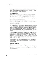
Страница 15: ... position the range button sets the attenuation to 500X In the lowered position the range button sets the attenuation to 50X Use the 500X position for measurements up to a maximum of 1 300 V DC peak AC differential Use the 50X position for better signal resolution on connections below 130 V DC peak AC Overrange Indicator The overrange indicator lights red if the voltage of the input signal exceeds...

Страница 16: ...ead length NOTE Above 10 MHz the extension leads degrade the high frequency performance of the P5205 probe See Figure 4 on page 14 Plunger Clamps The plunger clamps have long sleeves with retracting hooks These clamps connect safely to recessed test points that are otherwise difficult to reach The connectors are double insulated for safety Crocodile Clips The large insulated clips connect easily t...

Страница 17: ... measurement Install or remove the case by opening the access doors on the back When not in use coil the leads and secure them with the strap on the back Use one of the loops to hang the probe on a storage hook or utility belt Color Marker Bands When you are using more than one probe the bands enable you to quickly distinguish between probes and the channels they are connected to To use the marker...

Страница 18: ...o 50X If the overrange indicator lights or flashes the output signal may not be accurate Use the 500X setting instead 3 The probe output is adjusted to zero at the factory Adjust the probe output to zero only if you need to measure small differen tial voltages Follow steps a and b to make the adjustment a Let the probe warm up for at least 20 minutes b Connect the input leads of the probe together...

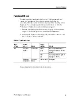
Страница 19: ...page 27 1 Use the installation procedure starting on page 6 to connect the output of the P5205 probe to a measurement instrument 2 Connect the inputs set the range and perform the check as each line of Table 1 below indicates Table 1 Functional check Input 1 or Input 2 or Mode Range setting Check Hot Ground or Neutral Differential 500X out Measurement instrument displays or indicates the line volt...

Страница 20: ...Getting Started 8 P5205 Instruction Manual ...

Страница 21: ... safety precautions described in the user and service manuals for the equipment you are working on Some general rules about using and servicing electrical equipment are worth repeating here H Observe the safety instruction symbols for the equipment you are working on H Consult the instruction or service manuals for the equipment you are working on H Don t operate or service an electrical device in...

Страница 22: ...cy RF burns If you need to use the probe within the risk area for RF burn power down the source before connecting or disconnecting the probe leads Maximum Input Limits CAUTION To avoid damaging the input circuitry of the P5205 probe do not apply a voltage that is more than 1 000 VRMS CAT II between either input and ground or more than 1 300 V DC peak AC between the two inputs Above 3 MHz the volta...

Страница 23: ...input and earth ground Operating Characteristics and Probing Techniques This section explains the operating characteristics of the High Voltage Differential Probe along with techniques you can use to maximize the performance of the probe Operating Limits The P5205 probe has two operating ranges that you select with the ATTENUATION button on the front panel H Select the 50X range for inputs of 0 V ...

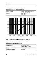
Страница 24: ...are common to both inputs More precisely CMRR is the ratio of the differential gain to the common mode gain The higher the ratio the greater the ability of probe to reject common mode signals For exact specifications see pages 15 and 17 Common mode rejection decreases as the input frequency increases Figure 5 on page 18 is a plot of typical CMRR of the probe versus input frequency For example if y...

Страница 25: ...e input leads are the same length The extension leads however do affect the high frequency performance of the probe With longer lead length differential noise induced into the input leads is greater Also because of the added inductance of the leads voltage measurements at frequencies above approximately 10 MHz may not be as precise Figure 4 on page 14 shows the affect on HF transient response The ...

Страница 26: ...nto the circuit Frequency and impedance of the source determine how much the probe loads the circuit you are measuring As the frequency of the source starts to increase beyond 1 kHz the input impedance of the probe begins to decrease The lower the impedance of the probe relative to that of the source the more the probe loads the circuit under test For a graph of frequency versus input impedance re...

Страница 27: ...cations for the P5205 probe fall into three categories warranted typical and nominal characteristics WARNING Special fixtures are required to examine specifications at the maximum frequency and voltage levels and should be conducted only by qualified Service Personnel See the Service section for more detail Warranted Characteristics Warranted characteristics in Tables 2 and 3 describe guaranteed p...

Страница 28: ...ompliances EC Declaration of Conformity Low Voltage Compliance was demonstrated to the following specification as listed in the Official Journal of the European Communities Low Voltage Directive 73 23 EEC as amended by 93 68 EEC EN 61010 1 A2 1995 Safety requirements for electrical equipment for measurement control and laboratory use EN 61010 2 031 1994 Particular requirements for hand held probe ...

Страница 29: ...ment is usually cord connected CAT I Secondary signal level or battery operated circuits of electronic equipment Pollution Degree 2 Do not operate in environments where conductive pollutants may be present Typical Characteristics Typical characteristics in Tables 4 and 5 describe typical but not guaranteed performance Table 4 Typical Electrical Characteristics Rise Time 3 5 ns Bandwidth Limit 5 MH...

Страница 30: ...range only Zero Adjust 50X 0 5 V 500X 5 V 90 dB 1 Hz 100 Hz 10 Hz 1 kHz 10 kHz 100 kHz 1 MHz 40 dB 50 dB 60 dB 70 dB 80 dB Frequency Figure 5 Typical Common Mode Rejection Ratio 50X Attenuation Table 5 Typical Mechanical Characteristics Dimensions Case 7 2 in 2 6 in 1 3 in 185 mm 66 mm 32 mm Dimensions Input Leads 12 in 30 cm Dimensions Output Cable 6 ft 1 8 m ...

Страница 31: ... 1 M 100 k 10 k 1 k 100 Frequency Hz Figure 6 Input Impedance vs Frequency Nominal Characteristics Nominal characteristics in Table 6 on page 19 describe guaranteed traits but the traits do not have tolerance limits Table 6 Nominal Electrical Characteristics Input Type Balanced differential Output Type Single ended Source Impedance of 50 Ω drives 1 MΩ oscilloscope input Load impedance must be grea...

Страница 32: ...fications 20 P5205 Instruction Manual Table 6 Nominal Electrical Characteristics Cont Gain Switchable 1 50 50X and 1 500 500X Audible Overrange Audible over range sounds whenever ON and over range LED is lit ...

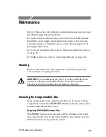
Страница 33: ...onix on page viii Cleaning Remove dirt with a soft cloth dampened in a mild detergent and water solution or isopropyl alcohol CAUTION To avoid damaging the probe use only a mild detergent and water solution or isopropyl alcohol do not use any other solvents or abrasive cleaners Do not immerse the probe Servicing the Compensation Box Some components of the compensation box can be serviced These com...

Страница 34: ...in out of the connector See Figure 7 No tools are required to install a replacement pin Insert a new pin into the connector socket as far as possible using finger pressure If necessary seat the pin into the connector by pressing the tip of the pin gently but firmly against a hard surface Figure 7 Replacing TEKPROBE interface pins ...

Страница 35: ... pull the interface collar off To replace the collar note the pin configuration on the compensation box and their holes in the interface collar The group of three pins fit through the smaller of the two holes in the interface collar See Figure 8 Align the tab to the slot and gently press the two pieces together See Figure 8 Once installed the TEKPROBE collar should rotate freely to lock and unlock...

Страница 36: ... of the compensation box 3 With both sides of the box open gently separate the two halves of the compensation box Cover catches Figure 9 Removing the compensation box covers Replacing the Compensation Box Covers To replace the covers follow these steps 1 Align the TEKPROBE interface and the strain relief notches with the tabs on the cover Refer to Figure 10 on page 25 2 Press the catches of the bo...

Страница 37: ... of a person that Tektronix may contact date of purchase and a description of the defect If the original packaging is unfit for use or not available use the following packaging guidelines 1 Select a sturdy shipping carton that has inside dimensions at least one inch greater than the probe dimensions 2 Put the probe into a plastic bag or wrap to protect it from dampness 3 Place the probe into the b...

Страница 38: ...Maintenance 26 P5205 Instruction Manual ...

Страница 39: ...are for use only by qualified personnel To avoid injury do not perform any servicing other than that stated in the operating instructions unless you are qualified to do so Refer to all safety summaries before performing any service WARNING ...

Страница 40: ......

Страница 41: ...A or TDS744A Display probe output Calibration generator Amplitude accuracy 0 75 Rise time 3 ns Wavetek 9100 with oscilloscope option Check probe attenuation rise time Calibrator Up to 500 VDC output Fluke 5100B Check common mode rejection ratio Plunger clamps 2 required Use clamps included in accessory kit Accessory kit 020 2106 00 Connection to binding post BNC adapter BNC male to dual binding po...

Страница 42: ...art number 103 0035 00 see Figure 11 Black and red plastic post covers Figure 11 BNC male to dual binding post adapter To expose the posts that you will connect the P5205 High Voltage Differential probe leads to remove the black and red plastic post covers of the BNC male to dual adapter Use a pair of pliers and a vise to remove the plastic covers as shown in Figure 12 on page 29 ...

Страница 43: ...puts of the P5205 probe Because this adapter has exposed metal surface only qualified personnel should perform testing with voltage levels that exceed 40 V rms Only qualified personnel should perform these procedures All pertinent safety rules and guidelines for elevated voltage measurements should be followed and adhered to Connect the output of the probe to the vertical input of the test oscillo...

Страница 44: ...gger output to channel 2 of the oscilloscope 2 Set the oscilloscope trigger edge source to channel 2 3 Set the volts division on both channels of the oscilloscope to 10 V 4 Set the sec div to 200 s and the acquisition mode to average 32 5 Connect the Modified BNC adapter to the output connector of the calibration generator 6 Attach the differential probe input leads without attachment accessories ...

Страница 45: ...epeat steps 9 and 10 14 Check that the vertical offset reads 9 7 to 10 3 V for the 3 gain accuracy 15 Reset the channel 1 vertical offset to zero Disable the output and leave setup connected for the next procedure Bandwidth 1 Connect the Modified BNC adapter through a 50 Ω terminator to the leveled sine wave output of the generator 2 Attach the differential probe input leads without attachment acc...

Страница 46: ...th the sliding ground spade on the calibrator 4 Attach the plunger clamps on the differential probe input leads 5 Twist the input leads together as shown in Figure 3 on page 13 and connect both probe inputs to the positive terminal of the calibrator 6 Adjust the offset on the probe output to zero 7 Set the output of the calibrator to 500 VDC 8 Enable the output 9 Check that the trace on the oscill...

Страница 47: ...trument type or model number H Instrument serial number H Instrument modification number if applicable If you order a part that has been replaced with a different or improved part your local Tektronix field office or representative will contact you concerning any change in part number You may exchange your module for a remanufactured module These modules cost significantly less than new modules an...

Страница 48: ...tes the part is good for all serial numbers 5 Qty This indicates the quantity of parts used 6 Name Description An item name is separated from the description by a colon Because of space limitations an item name may sometimes appear as incomplete Use the U S Federal Catalog handbook H6 1 for further item name identification 7 Mfr Code This indicates the code of the actual manufacturer of the part 8...

Страница 49: ...Replaceable Parts P5205 Instruction Manual 35 1 2 3 4 5 6 Figure 14 P5205 Probe and replaceable accessories ...

Страница 50: ...T CASE HOLDS PROBE IN CASE AS WELL AS SECURE ALL CORDS COMP BOX T 80009 016 1461 00 3 003 1433 00 1 SCREWDRIVER ADJUSTMENT TOOL METAL TIP PLASTIC BLACK TK2565 003 1433 00 4 016 0633 00 1 MARKER SET CA 2 EA VARIOUS COLORS 80009 016 0633 00 5 020 2106 00 1 ACCESS PKG 1 RED 1 BLACK CROCODILE CLIP 1 RED 1 BLACK INSULATED PLUNGER CLAMP 76545 KT 39411 6 020 2140 00 1 ACCESS PKG ACCESSORIES FOR P5205 765...

Страница 51: ...ial No Effective Serial No Discont d Qty Name Description Mfr Code Mfr Part Number 15 1 205 0191 00 1 SHELL ELEC CONN BNC ABS DOVE GRAY 80009 205 0191 00 2 131 3627 01 1 CONTACT ELEC GOLD PLATED TIP 18359 P 6158 1 3 206 0429 08 1 COMP BOX HALF TOP HALF COMP BOX W MACHINED HOLE PLASTIC P5205 80009 206 0429 08 4 334 9117 00 1 MARKER IDENT COMP BOX ID LABEL P5205 80009 334 9117 00 5 206 0430 00 1 COM...

Страница 52: ...ssories Optional Accessories Fig Index Number Tektronix Part Number Serial No Effective Serial No Discont d Qty Name Description Mfr Code Mfr Part Number 16 1 003 1383 00 1 RLSE TOOL COVER COMP BOX POLYCARBONATE TK2565 003 1383 00 1103 1 TEKPROBE IF PS W OFFSET 2 CONN 80009 1103 ...

Страница 53: ...ess City State Zip Code 18359 PYLON CO INC 51 NEWCOMB ST ATTLEBORO MA 02703 1403 76545 MUELLER ELECTRIC CO 1583 EAST 31ST ST CLEVELAND OH 44114 80009 TEKTRONIX INC 14150 SW KARL BRAUN DR PO BOX 500 BEAVERTON OR 97077 0001 TK2565 VISION PLASTICS INC 26000 SW PARKWAY CENTER DRIVE WILSONVILLE OR 97070 ...

Страница 54: ...Replaceable Parts 40 P5205 Instruction Manual ...

Отзывы: