background image

Appendix B: Specifications

372 User Manual

AĆ35

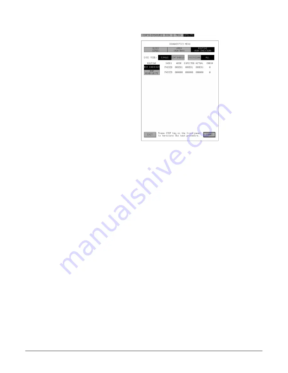
Figure AĆ9:ăSELF TEST Menu of the ROUTINE Level

Description of Menus

Menus of each level contain menus, soft buttons and status display zone as

shown below:

H

[EXIT] Soft Button - Ends the Diagnostic menu and returns to the

UTILITY menu. This soft button appears only when the [STOP] button

on the front panel can not be used to exit.

H

[START] Soft Button - Executes a self test according to the setting

conditions.

H

Level Selection Box - Moves the menu to the specified level. To move

from a higher level to lower one, select a test item in the Test Item selecĆ

tion box and then select a lower level in this selection box. To move from

a lower level to a higher one, select the level directly in this selection

box.

H

Test Item Selection Box - Selects a test item in the level indicated in the

Level selection box. Select here to change the level or execute a self

test. When ALL has been selected in the Group Exec selection box,

selection is ignored and the item to be tested is automatically highĆ

lighted.

Test item indicates the item displayed in each box of this selection box.

The test items are also called test block in BLOCK level, test area in

AREA level and test routine in ROUTINE level.

Содержание 372

Страница 1: ...User Manual 372 Semiconductor Workbench 070 8467 00 Please check for change information at the rear of this manual First Printing JULY 1992 ...

Страница 2: ...Tektronix Holland NV Heerenveen The Netherlands Instruments manufactured for Tektronix by external vendors outside the United States are assigned a two digit alpha code to identify the country of manufacture e g JP for Japan HK for Hong Kong IL for Israel etc Tektronix Inc P O Box 500 Beaverton OR 97077 Printed in U S A Copyright E Tektronix Inc 1992 All rights reserved Tektronix products are cove...

Страница 3: ...any other locations This warranty shall not apply to any defect failure or damage caused by improper use or improper or inadequate maintenance and care Tektronix shall not be obligated to furnish service under this warranty a to repair damage resulting from attempts by personnel other than Tektronix representatives to install repair or service the product b to repair damage resulting from improper...

Страница 4: ......

Страница 5: ...Ć lowed by Basic Menu Operation and how to mount a device The Reference section explains several topics in more detail including how to program the 372 with the help of examples on the floppy disk supplied with the manual The Appendices list the 372 accessories its specifications calibration and diagnostic procedures and other useful information The following documents are related to the use or se...

Страница 6: ...About this Manual ii ...

Страница 7: ... 1Ć3 Video Printer Centronics Plotter and TTL I O 1Ć3 Start Up 1Ć5 Safety 1Ć5 Operation 1Ć5 Power On 1Ć9 Self Test 1Ć10 Power Down 1Ć10 Tutorial 1Ć11 Introduction 1Ć11 Example 1 The Measurement Process 1Ć12 Powering Up and Initialization 1Ć12 Mounting a DUT 1Ć13 Setups 1Ć15 Configuration with CATALOG Setups 1Ć15 Averaging and Acquisition Parameters 1Ć16 Source Setup 1Ć18 Measurement and AutoĆscali...

Страница 8: ...ating Basics Basic Menu Operation 2Ć1 Touch Area 2Ć1 Box and Selection Box 2Ć1 Selectors 2Ć2 Soft Buttons 2Ć2 Soft Keys 2Ć2 Graphs 2Ć2 Other Areas 2Ć3 PopĆup Menu 2Ć3 Selector Operation 2Ć5 Entry of Text 2Ć6 Entry of Numerals 2Ć6 Moving Objects 2Ć7 Scrolling 2Ć9 Button Soft Button Operation 2Ć10 Mounting the Device Under Test 2Ć11 Attaching the Test Adapter 2Ć11 Mounting the DUT and Wiring 2Ć12 Pr...

Страница 9: ...NDU 3Ć21 Matrix Switch 3Ć21 Floating Chassis 3Ć21 Test Fixture 3Ć22 Protective Cover and Interlock System 3Ć22 DUT Connection and Kelvin Sense 3Ć22 Measurement Modes and Acquisition 3Ć24 Sweep Measurement Mode 3Ć24 Time Domain Measurement Mode 3Ć27 Averaging 3Ć27 Pulse Mode 3Ć28 Measurement Data and Graph Display 3Ć30 Curve Analysis 3Ć30 Range and Resolution 3Ć32 Setups 3Ć37 Introduction 3Ć37 Conf...

Страница 10: ...ment 3Ć70 Manual Scaling Adjustment 3Ć70 Y Axis Vertical Axis 3Ć70 Y Axis Range 3Ć71 X Axis Horizontal Axis 3Ć72 X Axis Range 3Ć73 Mathematical Operation 3Ć75 Introduction 3Ć75 Operation 3Ć75 Algorithm 3Ć76 Switching Graph Display 3Ć79 Parameter Analysis Using the Cursor 3Ć81 Introduction 3Ć81 Operation 3Ć81 Selecting Cursor and Cursor Type 3Ć82 Moving Cursor 3Ć82 Cursor Types 3Ć84 Zoom 3Ć95 Setup...

Страница 11: ...isk System 3Ć127 Introduction 3Ć127 Directories Files and Path 3Ć127 File Name 3Ć128 Reference of Files and Directories 3Ć128 Operation 3Ć129 Floppy Disk Handling Precautions 3Ć129 File Protection 3Ć129 Inserting a Floppy Disk 3Ć130 Removing a Floppy Disk 3Ć131 DISK Menu Overview 3Ć131 Outline of File Operations 3Ć133 Saving Settings Curves and Programs 3Ć134 Loading Settings Curves and Programs 3...

Страница 12: ...3Ć153 Program Structure 3Ć153 Flow Control 3Ć154 Register 3Ć155 Instruction Set 3Ć155 Sample Programs 3Ć161 Example 1 3Ć161 Example 2 3Ć163 Example 3 3Ć164 Example 3Ć1 PRG_BJT3 PRG 3Ć164 Example 3Ć2 PRG_BJT4 PRG 3Ć165 Example 4 3Ć166 GPIB 3Ć169 Connector and Cable 3Ć169 Configurations 3Ć170 Types of Devices 3Ć170 Restrictions 3Ć171 Functional Elements 3Ć171 GPIB Parameters 3Ć172 Device Addresses 3...

Страница 13: ...ing the Reference Voltage AĆ26 Calibration AĆ29 Self Test AĆ31 Check of Front Panel Control and TTL I O AĆ45 Appendix D Factory Initialization Settings AĆ51 ID vs VDS AĆ52 IDSS vs VDS AĆ53 IGSS vs VGS AĆ54 ID vs VGS AĆ55 gm vs VGS AĆ56 gm vs ID AĆ57 IC vs VCE AĆ58 ICBO vs VCBO AĆ59 IEBO vs VEBO AĆ60 BETA vs IC AĆ61 VCE VBE vs IC AĆ62 IC vs VBE AĆ63 IC vs IB AĆ64 IC IB vs VBE AĆ65 IB vs VCE AĆ66 IF...

Страница 14: ...Contents x ...

Страница 15: ...ion selection box CURSOR TYPE selector Cursor Type popĆup menu 1Ć23 Figure 1Ć17 ăPosition of Point 1 of the SLOPE Cursor 1Ć24 Figure 1Ć18 ăPosition of Point 2 of the SLOPE Cursor 1Ć25 Figure 1Ć19 ăFloppy Disk Drive 1Ć26 Figure 1Ć20 ăSAVE PopĆup Menu 1Ć27 Figure 1Ć21 ăCharacter Keypad PopĆup Menu 1Ć27 Figure 1Ć22 ăUTILITY menu and INITIALIZE soft button 1Ć28 Figure 1Ć23 ăCONFIG menu 1Ć29 Figure 1Ć2...

Страница 16: ... ăKnob Assignment Selection Box 2Ć8 Figure 2Ć7 ăScroll Operation 2Ć9 Figure 2Ć8 ăAn Example of a PopĆup Menu driven by Button Soft Button 2Ć10 Figure 2Ć9 ăInstallation of the Test Adapter and Mounting of the DUT 2Ć11 Figure 2Ć10 ăBJT Connection Example 2Ć13 Figure 2Ć11 ăFET Connection Example 2Ć14 Figure 2Ć12 ăDIODE Connection Example 2Ć15 Figure 2Ć13 ăConnection Example using INSULATED Test Adapt...

Страница 17: ... when the SLOPE Cursor is selected 3Ć86 Figure 3Ć34 ăINTERCEPT and INTERSECTION 3Ć87 Figure 3Ć35 ăApplication Menu when the XGONOGO Cursor is Selected 3Ć89 Figure 3Ć36 ăGONOGO Test Examples 3Ć91 Figure 3Ć37 ăApplication Menu when the YGONOGO Cursor is Selected 3Ć92 Figure 3Ć38 ăApplication Menu when the GAIN Cursor is Selected 3Ć94 Figure 3Ć39 ăZoom Application Menu and Graph Display 3Ć95 Figure 3...

Страница 18: ...lector 3Ć147 Figure 3Ć74 ăInsert Line PopĆup Menu 3Ć148 Figure 3Ć75 ăDelete Line PopĆup Menu 3Ć149 Figure 3Ć76 ăClear Lines PopĆup Menu 3Ć150 Figure 3Ć77 ăProgram Execution Control Buttons 3Ć150 Figure 3Ć78 ăTrace displays in the Program Trace Menu 3Ć152 Figure 3Ć79 ăGPIB Connector 3Ć169 Figure 3Ć80 ăGPIB System Configurations 3Ć170 Figure AĆ1 ă REFERENCE ADJUST Soft Button in the UTILITY Menu AĆ2...

Страница 19: ...m Selection 3Ć39 TableĂ3Ć12 ăMeasurement Mode Selection 3Ć44 TableĂ3Ć13 ăMaster Slave Selection 3Ć44 TableĂ3Ć14 ăMaster Sweep Mode Selection 3Ć45 TableĂ3Ć15 ăSlave Sweep Mode Selection 3Ć45 TableĂ3Ć16 ăX Y Axes Data Selection 3Ć47 TableĂ3Ć17 ăAveraging Mode Selection 3Ć49 TableĂ3Ć18 ăSampling Interval Range 3Ć50 TableĂ3Ć19 ăCurrent Range for Compliance 3Ć53 TableĂ3Ć20 ăVoltage Range for Compliance...

Страница 20: ... LPU AĆ6 TableĂAĆ7 ăNominal Traits AUX 1 2 AĆ7 TableĂAĆ8 ăNominal Traits Acquisition System AĆ7 TableĂAĆ9 ăNominal Traits Display and Touch Panel System AĆ8 TableĂAĆ10 ăNominal Traits Power Supply AĆ9 TableĂAĆ11 ăNominal Traits Interface AĆ9 TableĂAĆ12 ăNominal Traits Interlock System AĆ10 TableĂAĆ13 ăNominal Traits Kelvin Sensing AĆ10 TableĂAĆ14 ăNominal Traits Patch Panel Connectors AĆ10 TableĂA...

Страница 21: ... ăTypical Characteristics Mechanical AĆ23 TableĂAĆ33 ăTypical Characteristics Test Fixture AĆ23 TableĂAĆ34 ăTypical Characteristics Test Fixture Mechanical AĆ23 TableĂAĆ35 ăValue Selections AĆ28 TableĂAĆ36 ăMODE Selection AĆ30 TableĂAĆ37 ăSelf Test Items AĆ37 TableĂAĆ38 ăStatus and Event Messages AĆ69 TableĂAĆ39 ăTTL I O Connector AĆ71 TableĂAĆ40 ăVideo Printer Connector AĆ72 TableĂAĆ41 ăTest Fixt...

Страница 22: ...Contents xviii ...

Страница 23: ...practices that could result in personal injury or loss of life These two terms appear on equipment H CAUTION indicates a personal injury hazard not immediately acessible as one reads the markings or a hazard to property including the equipĆ ment itself H WARNING indicates a personal injury hazard not immediately accessible as one reads the marking H DANGER indicates a personal injury hazard immedi...

Страница 24: ... the 372 Danger Arising From Loss of Ground Upon loss of the protectiveĆground connection all accessible conductive parts including knobs and controls that may appear to be insulating can render an electric shock Use the Proper Fuse To avoid fire hazard use only the fuse of the correct type voltage rating and current rating as specified on the back of your product Do Not Operate in Explosive Atmos...

Страница 25: ...stances ou les manipulations qui peuvent endommager l appareil ou tout autre équipement associé Ce symbole indique où les précautions et autres informations applicaĆ bles se trouvent Ce symbole indique où les informations explicatives spéciales sont comprises dans ce manuel Il n y a pas de précautions ni danger associés avec cette information DANGER identifie les zones de risque immédiat pouvant e...

Страница 26: ...es accessibles y compris les molettes et commandes d apparence isolée peuvent entraîner un choc électrique Fusible Pour éviter tout risque d incendie n utiliser que le fusible recommandé pour votre appareil Les fusibles doivent toujours correspondre au type à la vitesse de furon en tension et en courant Ne pas utiliser l appareil dans une atmosphère explosive Pour éviter les explosions ne pas util...

Страница 27: ...e l appareil est mis à la masse L appareil fonctionne dans quatre gammes de tension d entrée 115 V BASSE TENSION 115 V HAUTE TENSION 230 V BASSE TENSION et 230 V HAUTE TENSION avec des fréquences allant de 48 0 à 63 0 Hz Avant de raccorder le cordon d alimentation au secteur vérifier la tension de la prise pour verifier que la tension est comprise dans la gamme de tension mentionnée sur l indicate...

Страница 28: ...Y comme interrupteur d alimentation de l appareil REMARQUE L interrupteur principal contrôle toute l alimentation CA de ce produit Le sélecteur ON STBY commande l alimentation de la plupart des circuits de l appareil mais continue à alimenter cerĆ tains circuits même lorsqu il est positionné sur STBY attente A la mise sous tension l appareil exécute un autotest Lorsque ce test est terminé l écran ...

Страница 29: ... Fixture REMARQUE Ne placer rien sur le couvercle protecteur Ne pas forcer le couvercle ou ne pas essayer de le fermer en plaçant un objet lourd dessus WARNING Pour éviter tout risque d électrocution ne pas fermer le capot de protection lorsque des fils dépassent du Text Fixture WARNING Le capot de protection peut devenir très chaud du fait de la chaleur émise par le DUT Pour éviter les accidents ...

Страница 30: ...Consignes de Sécurité Safety Summary xxvi ...

Страница 31: ...Getting Started ...

Страница 32: ......

Страница 33: ...to 100 volts or 0 to100 mA current Both SMUs are equipped with monitoring features that can deliver very small currents at a resolution of 25 fA at a current range of 100 pA The SMUs are provided with compliance and RĆmode Protective ResisĆ tance to protect the 372 and the DUT from overcurrent overvoltage and oscillation Measurement Configuration The 372 is equipped with an internal matrix switch ...

Страница 34: ...RT as characteristic curves The 372 is also provided with the features for processing of a graph on the CRT H AutoĆscaling automatically adjusts the graph to the optimum scale H Zoom enlarges selected portions of the curves displayed on the CRT H Math allows the display to be switched to the data that was calculated by a selected mathematical equation H Reference allows a curve stored in the stora...

Страница 35: ...save and load data settings and programs format a floppy disk and copy delete and rename files and directories 372ĆBased Programming The 372 has a powerful instruction set for programming Even complex measurement sequences can be completely automated The special proĆ gramming menu provides an editing feature for the creation and modificaĆ tion of a program and an execution trace feature for debugg...

Страница 36: ...Overview Getting Started 1Ć4 ...

Страница 37: ...oltage range shown by the voltage indication of the rear panel see Figure 1Ć1 If the settings of the line voltage selectors do not match the available line voltage refer this instrument to a qualified service person Principal Power Switch Fuse Line Voltage Indication Figure 1Ć1 ăLocation of the lineĆvoltage indication CAUTION Make sure that the reading of line voltage indication at the rear of the...

Страница 38: ...IEC 83 UL CSA A4 Switzerland 220 V 10 A SEV A5 ă ANSI Ċ American National Standards Institute ă NEMA Ċ National Electrical Manufacturers Association ă IEC Ċ International Electrotechnical Commission ă CEE Ċ International Commission on Rules for the Approval of Electrical Equipment ă BSI Ċ British Standards Institute ă AS Ċ Standards Association of Australia ă SEV Ċ Schweizerischer Elektrotechische...

Страница 39: ...propriate operating environĆ ment Specifications for temperature relative humidity altitude vibraĆ tions and emissions are included in Appendix B ăStep 5 ăTo prevent instrument damage from overheated components make sure the internal airflow is not blocked and check that the ventilaĆ tion holes on the bottom and side of the cabinet are not covered ăStep 6 ăConnect the Test Fixture to the 372 using...

Страница 40: ...1Ć3 ăConnection between the 372 and the Test Fixture ăStep 7 ăMake sure that the FLOATING terminal is connected to the GROUND terminal using the SHORTING BAR on the rear panel see Figure 1Ć4 Protective Ground Terminal Floating Terminal Shorting Bar Figure 1Ć4 ăFLOATING Terminal GROUND Terminal and SHORTING BAR ...

Страница 41: ...t the rear panel principal power switch to ON see Figureāā1Ć1 ăStep 9 ăSet the frontĆpanel ON STBY switch to ON see Figure 1Ć5 Once the 372 is set up use the ON STBY switch as the power switch of the instrument Start Up Menu ON STBY Switch Figure 1Ć5 ăON STBY Switch and Start Up Menu NOTE The principal power switch controls all AC power to the 372 The ON STBY switch controls power to most of the c...

Страница 42: ...he system is initialized and ready to be operated and to acquire data If the self test terminates with errors detected the Diagnostic menu see Figure 1Ć6 appears instead of the startup menu For self test diagnostics refer to Appendix C If the 372 does not operate normally turn the power off and then on again If the instrument still does not turn on properly refer it to a qualiĆ fied service person...

Страница 43: ... and DIODE are given H Example 4 describes how to setup and measure in time domain measurement A sample floppy disk with setup and program examples GPIB programming examples and sample devices 016Ć1216Ć00 including 1 1 N channel FET 2N4932 2 1 NPN type BJT 2N3904 3 1 Zener diode RD9 1E are provided with this manual Use these devices and or setup examples the four exercises mentioned above The setu...

Страница 44: ...ure 1Ć7 Voltage Steps Voltage Sweeps S G D VDS ID Figure 1Ć7 ăSimplified Measurement Circuit and Result of ID vs VDS Characteristic Powering Up and Initialization ăStep 1 ăSet the ON STBY switch on the front panel to ON see Figure 1Ć8ā After the self test the CONFIG menu will appear on the CRT A DUT Device Under Test can be mounted and various configurations and setups can now be performed Example...

Страница 45: ...tch Figure 1Ć8 ăPowerĆup and StartĆup Menu Mounting a DUT The following steps describe how to connect the supplied FET 2N4392 to the test fixture via an A1102 TOĆ952 TOĆ73P2 test adapter ăStep 2 ăAttach an A1102 TOĆ5 TOĆ3P test adapter to the test fixture see Figure 1Ć9 as follows ...

Страница 46: ...ush back the fasteners on the right and left sides of the test adapter ăStep 3 ăMount a DUT to the TOĆ5P socket of the test adapter ăStep 4 ăConnect the leads of the DUT to each channel with patch cords as shown in Figure 1Ć9 When measuring BJT FET or DIODE semiconductors the wiring must always be connected as indicated in Table 1Ć2 This table is also labeled to the inside of the protective cover ...

Страница 47: ...cific measurement by using the catalog setup feature The default parameter values for the acquisition and the source setup for each SMU are also set each time the catalog setup is performed so that you can easily step to the measurement stage by modifying some parameter values as needed ăStep 6 ăConfigure the 372 using the catalog setup menu See Figure 1Ć10 H Touch the CATALOG soft button located ...

Страница 48: ...est Item Selection Box Device Type Selection Box CATALOG Soft Button Figure 1Ć10 ăCatalog Setup Menu Averaging and Acquisition Parameters Operation Mode Setup Section AVERAGE Selector HOLD TIME Selector DELAY TIME Selector Figure 1Ć11 ăOperation Mode Setup ...

Страница 49: ...acquisitionĆrelated parameters if necessary see Figure 1Ć11 Delay time and hold time are used to delay the measurement by the specified time Both values are set to 0 in default Delay time and hold time can be set using the DELAY TIME and HOLD TIME selector In this example however default values are used If the manual setup method see Example 2 is used and the values other than the default values a...

Страница 50: ...e HPU works as a power source unit which supplies sweep voltage to the drain of the FET and the LPU works as a step generaĆ tor which supplies stepped voltage to the gate of the FET In Source Setup the parameters that determine the shape of sweep voltage and stepped voltage must be set as well as the parameters to determine operating conditions such as measuring range voltage upper limit and R mod...

Страница 51: ...HPU INCREMENT Numeric 0 025 V HPU MEASURE RANGE Box 100 mA COMPLIANCE Numeric 30 mA RESISTANCE Box 0 kW ăStep 9 ăModify the default values Every time the catalog setup is made the default source values of the HPU and LPU are set If needed modifications must be made dependĆ ing on the measurement to be performed In this example the setup values shown in Table 1Ć3 are used First compare the setup va...

Страница 52: ...le To input 0 25 V to the INCREMENT selector of the LPU touch the following keys in order 0 2 5 It is not necessary to input the unit value When a selection popĆup menu appears touch the selection box with the desired value to set the parameter Refer to Figure 1Ć13 and Figure 1Ć14 for the numeric keypad popĆup menu and selection type popĆup menu respectively Numeric Keypad PopĆup Menu STOP Selecto...

Страница 53: ... box in the major menu selection box in upper part of the CRT to display the MEASURE menu see Figure 1Ć9 ăStep 11 ăPress the SINGLE button on the front panel to initiate meaĆ surement When the measurement begins the SINGLE indicator lights and the measurement curves are displayed on the graph of the MEASURE menu When measurement is completed the SINGLE indicator goes out see Figure 1Ć15 ăStep 12 ă...

Страница 54: ...S curves Below are procedures to obtain Rds near 0 0 V of drain voltage at 0 0 V of gate voltage Selecting Cursor ăStep 13 ăActivate the cursor feature and select the SLOPE cursor see Figure 1Ć16 H Touch the CURSOR box in the Application selection box to activate the cursor feature H Touch the CURSOR TYPE selector to display the Cursor Type popĆup menu H Touch the SLOPE box in the popĆup menu to d...

Страница 55: ...In this case two points are moved simultaneously The method of movement must be selected before moving the point The points of the cursor can be easily reĆpositioned by touching the desired position on the graph The position of the cursor point can then be fineĆ tuned using the general purpose knob Now measure the slope of the first curve at 0 0 V of gate voltage ăStep 14 ăPosition point 1 of the ...

Страница 56: ... at the point where the X axis compoĆ nent is 0 0 V Point 2 Knob Assignment Selection Box MOVE Selector Point 1 Figure 1Ć17 ăPosition of Point 1 of the SLOPE Cursor ăStep 15 ăReĆposition point 2 of the SLOPE cursor see Figure 1Ć12 H Touch the MOVE selector to display the MOVE popĆup menu H Touch the POS 2 W DATA1 box to switch the positioning control from point 1 to point 2 and to move the point 2...

Страница 57: ...aved in a disk file so they can be retrieved later ăStep 17 ăFormat a MSĆDOS 3 5Ćinch floppy disk and insert it into the disk drive see Figure 1Ć19 In this case do not use the supplied disk ăStep 18 ăPress the SAVE button on the front panel to display the SAVE popĆup menu see Figure 1Ć20 ăStep 19 ăTouch the SETUP box in the TYPE selection box to select the data type to be saved The file extension ...

Страница 58: ...u touch the soft keys I D _ V D S in order followed by touching the ENTER soft button to enter the file base name ID_VDS to the NAME selector ăStep 21 ăTouch the EXECUTE soft button to start saving The LED indicator lights to indicate that data is being saved to the floppy disk Wait until the LED indicator goes out before removing the floppy disk Eject Button LED Indicator Figure 1Ć19 ăFloppy Disk...

Страница 59: ...orial The Measurement Process 372 User Manual 1Ć27 EXECUTE Soft Button NAME Selector TYPE Selection Box SAVE PopĆup Menu SAVE Button Figure 1Ć20 ăSAVE PopĆup Menu Figure 1Ć21 ăCharacter Keypad PopĆup Menu ...

Страница 60: ...on Display the CONFIG menu after resetting to the default state ăStep 1 ăInitialize the instrument and display the CONFIG menu H Display the UTILITY menu by touching the UTILITY box in the main menu selection box see Figure 1Ć22 H Touch the INITIALIZE soft button located at the lowerĆright of the CRT The INITIALIZE menu appears to the left of the INITIALIZE soft button H Touch the EXECUTE soft but...

Страница 61: ...e the source mode of the HPU and LPU There are two source modes I mode which works as a regulated current supply and V mode which works as a regulated voltage power supply SOURCE MODE Selectors CONNECTION Selector Figure 1Ć24 ăConnection Setup and PopĆup Menu ăStep 2 ăConnect HPU LPU and GNDU to the CH1 CH2 and CH3 as follows H Touch the CONNECTION selector to display the Connection popĆ up menu s...

Страница 62: ...uch the V box after selecting the SOURCE MODE selector on the CH2 side to set the LPU connected to CH2 to V mode Measurement Mode In Operation Mode Setup either sweep measurement mode or time domain measurement mode can be selected The sweep measurement mode is used to apply a swept voltage or current in a staircase manner and measure the voltage and or current response characteristics The time do...

Страница 63: ... is also set and a round sweep is made for each sweep Sweep Mode In the measurement of ID vs VDS the voltage sweep applied to the drain must be performed once for each voltage step of the gate The LPU is arranged as a slave to the HPU ăStep 5 ăSet the HPU to master source for VDS drainĆtoĆsource voltage sweep and the LPU to slave source for stepped output see Figure 1Ć26 as follows H Touch the MAS...

Страница 64: ...inĆtoĆsource voltage as the X axis component data and ID drain current as the Y axis component data see Figure 1Ć27 H Touch the X DATA selector to display the XĆDATA popĆup menu H Touch the HPUV box in the popĆup menu to select HPU voltage VDS as the X axis component H Touch the Y DATA selector to display the YĆDATA popĆup menu H Touch the HPUI box in the popĆup menu to select HPU current ID as th...

Страница 65: ...ing does not effect the measurement ăStep 10 ăTouch the MEASURE box in the major selection box in the upper part of the CRT to display the MEASURE menu on the CRT see Figure 1Ć28 Y LABEL Selector X LABEL Selector Figure 1Ć28 ăMEASURE menu ăStep 11 ăLabel the X axis VDS and the Y axis ID see Figure 1Ć28 as follows H Touch the X LABEL selector to display the character keypad popĆ up menu H Touch the...

Страница 66: ... the sample floppy disk supplied with this manual Setup files are located in directory FET with the file name of ID_VDS SET ăStep 1 ăInsert the supplied disk into the disk drive see Figure 1Ć19 ăStep 2 ăChange the current working directory to FET so the 372 can access the ID_VDS SET file H Display the DISK menu by touching the DISK box in the main menu selection The floppy disk files appear as sho...

Страница 67: ...ection box can be seen ăStep 5 ăSelect the file ID_VDS SET by touching the box labeled in the File selection box ăStep 6 ăTouch the EXECUTE soft button on the popĆup menu to start loading The popĆup menu will disappear The LED indicator lights to indicate that the data is being loaded from the floppy disk Wait until the LED indicator goes out before removing the floppy disk ăStep 7 ăPress the SING...

Страница 68: ...ial Other ways to Setup Getting Started 1Ć36 General Purpose Knob Setup File Currently Selected for Loading File Selection Box LOAD Button Figure 1Ć30 ăLOAD PopĆup Menu Recall of the settings is now complete ...

Страница 69: ...ings and measured curves are shown in the figures They can also be obtained from the disk supplied with the manual To measure curves for each example mount the device in the test fixture wire the patch cords shown in Figure 1Ć9 for the FET or in Figure 1Ć31 and Figure 1Ć32 for the BJT and DIODE Then follow the procedures described in Recalling Settings in Example 2 for loading the settings from a ...

Страница 70: ...ayed on the CRT If not touch the MEAĆ SURE box in the major menu selection box see Figure 1Ć33 5 The Cursor application menu is shown in the application section box lower part of the MEASURE menu If not touch the CURSOR box in the application selection box see Figure 1Ć33 Major Menu Selection Box Application Selection Box Figure 1Ć33 ăMajor Menu and Application Selection ...

Страница 71: ...is located in the directory BJT of the floppy disk Figure 1Ć34 ăSettings for IC IB vs VBE To measure the slope of the base current ăStep 1 ăActivate the cursor feature and select the SLOPE cursor see Figure 1Ć35 H Touch the CURSOR box in the application selection box to activate the cursor feature H Touch the CURSOR TYPE selector to display the Cursor Type popĆup menu H Touch the SLOPE box in the ...

Страница 72: ...splay the MOVE popĆup menu H Touch the POS1 W DATA2 box to move point1 of the SLOPE cursor along the curve If point 1 is placed on the IC curve in the graph the POS1 W DATA1 box must be selected H Touch the area on the curve as close to the target point as possible H Confirm the NEXT box is selected in the knob assignment selecĆ tion box If not touch the NEXT box so point1 will move along the curv...

Страница 73: ...the POS2 W DATA2 box to switch the positioning control from point 1 to point 2 and to move point 2 along the curve When point 1 is placed on the IC curve in the graph the POS2 W DATA1 box must be selected H Touch the area on the curve as close to the target point as possible H Turn the knob to adjust the position of cursor point 2 with respect to the X axis ăStep 4 ăRead out the results In Figure ...

Страница 74: ...he SLOPE Cursor and Readout Measuring hFE Figure 1Ć38 shows the settings for the IC vs VCE characteristic of a BJT 2N3904 and its measured curves From these curves hFE is calculated at a specified collectorĆemitter voltage using the GAIN cursor The setup file IC_VCE SET is located in the directory BJT on the sample disk ...

Страница 75: ...pe of the Base Current of a BJT ăStep 2 ăTouch the area on the curve as close to the target point as possible to position the GAIN cursor and to select the lowest point of the GAIN cursor ăStep 3 ăAdjust the position of the GAIN cursor with respect to the X axis the same way as in step 4 of Measuring Slope of the Base Current ăStep 4 ăRead out the results In Figure 1Ć39 155 0 is displayed for GAIN...

Страница 76: ...T Measuring Transconductance gm Figure 1Ć40 shows the settings for ID vs VGS of a FET 2N4392 and its curves The smallĆsignal transconductance gm delta ID delta VGS can be obtained from the slope of these curves The setup file ZD_VGS SET for this measurement is located in the directory FET on the sample disk ...

Страница 77: ... ăActivate the cursor feature with the CURSOR selector and select the SLOPE cursor as in step1 of Measuring Slope of the Base Current of a BJT ăStep 2 ăPosition point 1 of the SLOPE cursor moving it along the curve ăStep 3 ăPosition point 2 of the SLOPE cursor as moving it along the curve ăStep 4 ăRead out the results In Figure 1Ć41 15 000 mS is displayed for GRAD Therefore the smallĆsignal transc...

Страница 78: ...rrent at Specified Voltage Figure 1Ć42 shows the example of the setups and measured curves of IF vs VF characteristic of a DIODE RD9 1E From these curves absolute current is obtained at specified voltage using DOT cursor The setup file IF_VF SET for this measurement is located in the directory DIO on the sample disk ...

Страница 79: ...of Measuring Slope of the Base Current of a BJT ăStep 2 ăTouch the area on the curve as close to the target point as possible to position the DOT cursor ăStep 3 ăAdjust the position of the GAIN cursor with respect to the X axis the same way as in step 4 of Measuring Slope of the Base Current of a BJT ăStep 4 ăRead out the results In Figure 1Ć43 7 3050 mA is displayed for Y Therefore the current at...

Страница 80: ...Tutorial Measurements Using the Cursor Getting Started 1Ć48 Figure 1Ć43 ăDOT Cursor and Readout ...

Страница 81: ...almost the same as the circuit for the ID vs VDS measurement The catalog setup feature is used to set up the 372 for sweep measurement but the connection of the configuration can be performed the same way for time domain measurement This setup is deĆ scribed below When manual setup is required refer to Connection and Source Mode in Example 2 Connection and Source Mode ăStep 1 ăSet the connection a...

Страница 82: ...d Test Item Selection Box Device Type Selection Box CATALOG Soft Button Figure 1Ć45 ăCatalog Setup Menu Measurement Mode AVERAGE Selector INTERVAL Selector HOLD TIME Selector MEASURE MODE Selector Figure 1Ć46 ăOperation Mode Setup ăStep 2 ăSet the 372 to time domain measurement mode as follows H Touch the MEASURE MODE selector to display the Measure Mode popĆup menu see Figure 1Ć46 ...

Страница 83: ...Ć46 ăStep 3 ăSet the sampling interval and hold time as follows H Touch the INTERVAL selector see Figure 1Ć46 to display the numeric keypad popĆup menu H Touch the soft keys 1 0 0 m and the ENTER soft button to set the sampling interval to 100 ms H Touch the HOLD TIME selector to display the numeric keypad popĆup menu H Touch the soft keys 1 0 0 and the ENTER soft button to set the hold time to 10...

Страница 84: ...d to another setting these steps can be omitted Source Setup Actual operation values of each SMU must be set The start and stop value of the HPU and LPU are the value at which the measurement starts and the value set in the hold time after measurement starts see Figure 1Ć48 ăStep 6 ăWith the selectors in the Source Setup section set the source parameters The relationships between various source se...

Страница 85: ...ay the MEASURE menu on the CRT ăStep 8 ăDefine the Y axis label as follows H Select the Y LABEL selector see Figure 1Ć49 to display a characĆ ter keypad popĆup menu H Touch the soft keys I D and the ENTER soft button The popĆup menu disappears and ID is displayed in the Y LABEL selector ăStep 9 ăWith the Y TOP Y BOTTOM X LEFT and X RIGHT selecĆ tors see Figure 1Ć49 set the scale of the X and Y axi...

Страница 86: ...aph for Time Domain Measurement Measurement ăStep 10 ăPress the SINGLE button on the front panel to initiate the measurement The Single LED indicator lights when the measurement starts When the X axis has been set to NO SCROLL in the Graph Display Setup section of the MEASURE menu a maximum of 4000 data points can be meaĆ sured and displayed in the graph ...

Страница 87: ...Tutorial Ć Time Domain Measurement 372 User Manual 1Ć55 SINGLE Button Figure 1Ć50 ăMeasurement Example ...

Страница 88: ...ram file which repeats loading and executing meaĆ surement for 1 through 5 BJT 1 IC_VCE SET Setup file for IC vs VCE characteristic measurement 2 BETA SET Setup for log beta vs log IC characteristic measureĆ ment 3 VCEBE_IC SET Setup file for log VCE log VBE vs log IC characĆ teristic measurement 4 IC_VBE SET Setup file for log IC vs log VBE characteristic meaĆ surement 5 IC_IB SET Setup file for ...

Страница 89: ...s a setup file and executes measurement for 1 through 4 Before loading a setup file the program goes into a paused state waiting for the START button to be pressed 6 PRG_DIO2 SET Program file which repeats loading and executing meaĆ surement for 1 through 4 To load a program file and control program execution refer to Programming Examples in 372ĆBased Programming Before executing a program the dev...

Страница 90: ...Tutorial Ć About the Sample Disk Getting Started 1Ć58 ...

Страница 91: ...Operating Basics ...

Страница 92: ......

Страница 93: ... appropriate box selectors soft buttons or soft keys displayed on the menu see Figure 2Ć1 to perform a function Selection Box Selection Box Soft Buttons Selectors Soft Keys Figure 2Ć1 ăBoxes Selectors Soft Buttons and Soft Keys Box and Selection Box A box is a framed area with a light green background The box is an item that can be selected Multiple boxes are called a selection box Contents of the...

Страница 94: ...n be performed by touching the soft button Some soft buttons start execution of their function immediately when touched and others display a popĆup menu and start execution of the funcĆ tions after parameters are set in the popĆup menu The soft buttons in the first case have a heavy outline Soft Keys Soft keys are like soft buttons Soft keys represent numeric keys or characĆ ter keys on the keypad...

Страница 95: ...buttons The latter will be described in detail later Only popĆup menus enabled by selectors are described here There are 3 types of popĆup menus that appear with selectors H Selection Box popĆup menu H Numeric keypad popĆup menu H Character keypad popĆup menu Selection Box PopĆup Menu Figure 2Ć3 shows an example of this type of popĆup menu which has multiĆ ple boxes An item indicated by a box that...

Страница 96: ...acter at the cursor position and shifts the characters on the right side of the cursor toward the left When this key is positioned on the rightĆmost character of the text it works as a back space key The CLEAR soft key clears the text on display field H Soft Keys that move the cursors The and soft keys move the cursor position in the display field to the right and to the left H Soft Buttons To dis...

Страница 97: ... soft button The selector is still active Touching either soft button causes the popĆup menu to disappear Selector Operation As described before the selector can be entered or selected via a popĆup menu that appears when you touch that selector There are three types of input depending on the invoked popĆup menu H Selection of Item H Entry of Text H Entry of Numerals Selection of Item The item box ...

Страница 98: ...anged Touching either soft button causes this popĆup menu to disappear Entry of Numerals Numerals can be entered via the numeric keypad popĆup menu or with the general purpose knob Entry with Numeric Keypad PopĆup Menu ăStep 1 ăTouch the selector to bring up the numeric keypad popĆup menu see the right side of Figure 2Ć4 ăStep 2 ăEnter the numerics and prefix symbols in the display field by touchi...

Страница 99: ...played increases It decreases by turning the knob counterclockwise The knob entry mode stays in effect until the next action touching the CRT is taken Selector in Knob Entry Mode General Purpose Knob Figure 2Ć5 ăSelector in Knob Entry Mode Moving Objects You can move labels cursors and the zoom window on the graph in the MEASURE menu by either by touching a new place on the graph or by turning the...

Страница 100: ...s selection box to assign horizontal movement to the general purpose knob touching the VERT box to assign vertical movement General Purpose Knob Knob Assignment Selection Box Figure 2Ć6 ăKnob Assignment Selection Box ăStep 2 ăFineĆtune the position with the general purpose knob NOTE When a selector is touched while the knob assignment selection box is being displayed the soft button shown below ma...

Страница 101: ...AGE FORWARD and PAGE BACKWARD soft buttons are displayed together with the general purpose knob icon as shown in Figure 2Ć7 You can scroll with the soft buttons or with the general purpose knob H Scroll with General Purpose Knob Turn the knob clockwise for forward scrolling and counterclockwise for reverse scrolling In this case one line is scrolled for every 1 25 rotation The FINE button is not e...

Страница 102: ...appear when this type of button soft button is touched The following procedure is valid for most popĆup menus ăStep 1 ăTouch the button on the front panel or the soft button on the menu to bring up the popĆup menu See Figure 2Ć8 ăStep 2 ăSet the appropriate parameter in the popĆup menu by selecting the item in the selection box or by entering a value on the popĆup menu driven by the selector ăStep...

Страница 103: ... DUT does not fit in the Test Adapter or in the Test Fixture an external test fixture may be required Refer to a qualified service personnel for construction of an external test fixture G D S G D S Fastener Figure 2Ć9 ăInstallation of the Test Adapter and Mounting of the DUT Attaching the Test Adapter ăStep 1 ăAttach a test adapter to the test fixture see Figure 2Ć9 as follows H Pull up on the fas...

Страница 104: ...ach channel the supplied patch cords For more details about wiring refer to Basic Patch Wiring Examples deĆ scribed later Protective Cover ăStep 4 ăClose the protective cover Carry out the measurements with the protective cover closed and avoid touching the cover during measurements The output indicator is always lit when the cover is closed An interlock disables measurements when the cover is ope...

Страница 105: ...rds must be connected as indicated in Table 2Ć1 This table is also shown on the inside of the protective cover of the test fixture and in the popĆup menu brought up by touching the README soft button located in the upper right of the CONFIG menu TableĂ2Ć1 ăConnections of the DUT leads CH 1 CH 2 CH 3 FET Drain Gate Source BJT Collector Base Emitter DIODE Anode Cathode Samples of basic connections b...

Страница 106: ...ions between a BJT and the test panel Connect CH1 CH2 and CH3 to collector base and emitter respecĆ tively G D S G D S Figure 2Ć11 ăFET Connection Example Figure 2Ć11 shows an example of connections between an FET and the test panel Connect CH1 CH2 and CH3 to drain gate and source respectively ...

Страница 107: ...athode respectively Klip Chip Figure 2Ć13 ăConnection Example using INSULATED Test Adapter Figure 2Ć13 shows an example that uses an insulated test adapter provided as an optional accessory for measuring high resistance For information on how to use the PLATE terminal of the Test Adapter and GUARD terminal on the patch panel refer to DUT Connection and Kelvin Sense in Setups and Measurement of the...

Страница 108: ...Mounting the Device Under Test Operating Basics 2Ć16 ...

Страница 109: ...d may have an effect on the measurement or when noise may be introduced via a ground loop ăStep 1 ăDisconnect the floating terminal from the ground terminal by removing the shorting bar on the rear panel see Figure 2Ć14 WARNING To avoid electrical shock do not touch the floating terminal while the shorting bar is being removed ăStep 2 ăAfter the floating measurement is performed be sure to connect...

Страница 110: ...Before and After Floating Measurement Operating Basics 2Ć18 ...

Страница 111: ...Reference ...

Страница 112: ......

Страница 113: ...and purposes of various connectors and terminals on the rear panel The Test Fixture contains overview of the test fixture test panel rear panel and test adapter each of which shows the location and purposes of the various connectors The Menu and Touch Panel contains configuration of display zone CONFIG menu Catalog Setup menu MEASURE menu DISK menu PROG menu and UTILITY menu each of which shows th...

Страница 114: ...At a Glance Reference 3Ć2 CRT with Touch Panel System CRT Brightness Setup page 3Ć123 Floppy Disk Drive page 3Ć127 LED indicator lights when the drive is active ON STBY Switch Front Panel ...

Страница 115: ...r unlocks the touch panel system TOUCH PANEL Indicator lights in green when unlocked indicator is lit in green SAVE saves settings curves and program into floppy disk file page 3Ć134 LOAD loads settings curves and programs from floppy disk file page 3Ć135 CALIBRATION performs calibration page AĆ29 CALIBRATION Indicator blinks during calibration HARDCOPY performs CRT hardcopy page 3Ć111 HARDCOPY In...

Страница 116: ...onnectors provide SENSE and FORCE lines connected to the Test Fixture page 3Ć22 This connector is reserved for future use Floating ground terminal provides floating chassis ground connection for floating measurement Protective Ground Terminal Shorting Bar provides interconnection between the floating ground terminal and the protective ground terminal page 1Ć8 and 2Ć17 Rear Panel ...

Страница 117: ...Floating Unit page 1Ć7 CENTRONICS Connector provides connection to a printer with an ESC P function CRT hardcopy page 3Ć111 GPIB Connector Remote Control refer to Programmer Manual CRT hardcopy to HPGL plotter page 3Ć169 Line Voltage Selector sets the voltage range to match the electrical system page 1Ć7 TTL I O Connector provides TTL level signal IN OUT function Connector pinout and signal defini...

Страница 118: ...t a Glance Reference 3Ć6 Test Adapter page 2Ć11 Patch Panel DUT Standard Connection Label Protective Cover page 2Ć12 Optional Accessory Test Adapter placed in Patch Panel Test Fixture with Test Adapters ...

Страница 119: ...low you to connect a power supply pattern generator or other device to provide signals to the DUT Signals up to 40 Vpk and 200 mA can be supplied to this connector TEST FIXTURE Connector provides connection to the instrument page AĆ73 SENSE and FORCE Connectors provide connections to SENSE and FORCE lines of the instrument page 3Ć22 Rear Panel of the Test Fixture ...

Страница 120: ... terminals page 3Ć22 For wiring to the DUT page 2Ć13 CHASSIS provides protective ground This terminal is connected to the instrument via the Test Fixture cable AUX provides auxiliary voltage These terminals are connected to the AUX1 and AUX2 units on the instrument via the Test Fixture cable HOOKUP Section provides hookup for wiring Three terminals in 1 are common and three terminals in 2 are comm...

Страница 121: ...chanism DIODE SOTĆ23 Test Adapter for axialĆlead diodes and SOTĆ23 surface mount transistors Only the socket for diode is provided with a kelvinĆsensing mechanism INTEGRATED CIRCUIT Test Adapter for 20Ćpin ICs No kelvinĆsense mechanism is provided INSULATION BOARD Test Adapter optional accessory for DUTs that cannot be measured with other adapters and for DUTs that require a high level of insulati...

Страница 122: ...CONFIG box is selected CONFIG displays the CONFIG menu MEASURE displays the MEASURE menu DISK displays the DISK menu PROG displays the PROG menu UTILITY displays the UTILITY menu Message Display Zone displays an error message status message or event message according to the processing or operating status Major Menu Display Zone displays a major menu selected from Major Menu Selection Box Main Menu...

Страница 123: ...Ć44 Sweep Mode page 3Ć44 Acquisition Parameters and Averaging Mode page 3Ć49 Graph Display Setup Section page 3Ć47 AutoĆscaling page 3Ć70 Switching Graph Display page 3Ć79 MATH icon page 3Ć75 Miniature graph displays same contents as that of graph in MEASURE menu Touching miniature graph displays the MEASURE menu Source Setup Section page 3Ć51 README explains how to connect the leads of a DUT to e...

Страница 124: ...ction Measurement Mode page 3Ć43 Acquisition Parameters and Averaging Mode page 3Ć49 Graph Display Setup Section page 3Ć47 AutoĆscaling page 3Ć70 Switching Graph Display page 3Ć79 Source Setup Section page 3Ć51 CONFIG Menu Time Domain Measurement Mode ...

Страница 125: ... menu Test Item Selection Box selects the parameter to be measured depending on the selection of device type This selection together with the selection in Device Selection Box determines configuration page 3Ć39 Device Type Selection Box selects DUT type to be measured page 3Ć39 Catalog Setup Menu ...

Страница 126: ...om page 3 95 Application Selection Box SETUP provides setup feature page 3Ć67 MATH provides mathematical operation page 3Ć75 CURSOR provides cursor feature page 3Ć81 LABEL provides text editing feature page 3Ć99 ZOOM provides zoom feature page 3Ć95 Application Section TIME STAMP Display Field displays date and time page 3Ć121 Measure Menu ...

Страница 127: ...Ć26 INITIALIZE restores default states with some exceptions page 3Ć117 DISPLAY controls TIME STAMP and CRT brightness For TIME STAMP page 3Ć121 For CRT brightness page 3Ć123 HARDCOPY sets hardcopy environment page 3Ć111 IEEE 488 2 sets GPIB parameters For hardcopy page 3Ć111 For remote control refer to Programmer Manual ID Information page 3Ć125 Utility Menu ...

Страница 128: ...a Glance Reference 3Ć16 Trace Mode Selection Box selects single step trace mode or continuous trace mode page 3Ć151 Page Soft Buttons page 3Ć152 Program trace list display area PROG Menu Program Trace Menu ...

Страница 129: ...149 INSTRUCTION Selectors define program statements page 3Ć146 EDIT TRACE selects program editing menu or program trace menu Page Soft Buttons and LINE Selector control the program display area page 3Ć146 Program Edit insert or delete program lines PROG Menu Program Editing Menu ...

Страница 130: ... of the disk and also shows number of files in the current working directory MAKE DIR Soft Button page 3Ć136 COPY FILE Soft Button page 3Ć137 CHANGE DIR Soft Button page 3Ć136 REMOVE FILE DIR Soft Button removes file and or directory page 3Ć138 RENAME FILE DIR Soft Button page 3Ć139 FORMAT DISK Soft Button page 3Ć139 Disk Menu ...

Страница 131: ... GNDU Ground Unit H AUX 1 Auxiliary 1 and AUX 2 Auxiliary 2 and H Matrix Switch for connecting HPU LPU and GNDU to a DUT The configuration of the measurement system is shown in Figure 3Ć1 HPU LPU GNDU AUX1 AUX2 Test Fixture Matrix Switch Floating Chassis Shorting Bar Figure 3Ć1 ăMeasurement Circuit Block Diagram Measurement Circuit ...

Страница 132: ...h the test item Also upperĆlimit values usually called Compliance for current and voltage can be set arbitrarily The Current Monitor Circuit monitors current output from the IV amplifier so that the IV amplifier can send regulated current to the DUT The Sensing Resistance Rs of this circuit can automatically or manually be switched in accordance with the current through the DUT The Voltage Monitor...

Страница 133: ...SENSE FORCE Zero Potential Level Figure 3Ć3 ăGNDU Simplified Circuit Matrix Switch The Matrix Switch connects the HPU LPU and GNDU to the three channels of the DUT The 372 has a catalog setup feature which automatically configĆ ures the appropriate DUT type and test item For details refer to ConfiguraĆ tion in Setups Floating Chassis As is shown in Figure 3Ć1 the measurement circuit is separated f...

Страница 134: ...ctors of the Test Fixture such as power supply or signal generator on or off DUT Connection and Kelvin Sense The DUT is mounted to the 372 via the test adapter and the Test Fixture The circuit of the Test Fixture and the test adapter A1101 TOĆ92 TOĆ72 are shown in the Figure 3Ć4 Each channel has three lines FORCE SENSE and GUARD H FORCE Line An output line from either the LPU or the HPU The FORCE ...

Страница 135: ... LOW LID SIGNAL DĆSUB 25 Pin CH1ĆSENSE CH1ĆFORCE CH2ĆSENSE CH2ĆFORCE CH3ĆSENSE CH3ĆFORCE EXT HIGH EXT LOW HOOK UP CHASSIS AUX 2 AUX 1 CH1ĆGUARD CH2ĆGUARD CH3ĆGUARD FORCE SENSE TOĆ92 1 2 3 4 TOĆ92 FORCE SENSE Test Fixture Circuit Test Adapter Circuit PLATE 1 2 3 4 Figure 3Ć4 ăTest Fixture and Test Adapter Circuit ...

Страница 136: ...ure 3Ć5 ăConnection to Socket Measurement can be performed in a sweep measurement mode or time domain measurement mode Sweep Measurement Mode The 372 does not only provide constant voltage and current to the DUT but it also allows the HPU and LPU to operate in sweep measurement mode For convenience the HPU and LPU have a master slave relationship when in sweep measurement mode When the master sour...

Страница 137: ... and slave source when the slave source is in sync and stepgen modes respectively is shown in Figure 3Ć6 and Figure 3Ć7 Output Value of Master Source Output Value of Slave Source Output Value of Slave Source Output Value of Master Source Offset Output Value of Master Source Output Value of Slave Source Output Value of Slave Source Output Value of Master Source x Ratio Ratio Relationship Between Sl...

Страница 138: ... H Increment The step voltage or current by which the sweep value increments or decrements In the case of a linear sweep the increment or decrement size is a constant value In the case of a log sweep the increment value varies according to the number of divisions per decade logarithmic equal interval When the slave source is in stepgen mode Step is characterized as follows H Start The start voltag...

Страница 139: ...rs in time domain measurement mode Stop Value Hold Time Time Sampling Interval Start Value Figure 3Ć8 ăVoltage or Current Changes vs Time H Start The voltage or current at which measurement starts H Stop The voltage or current set in the hold time after measurement starts H Hold Time The time length that the START value is maintained after measurement begins The voltage or current value is changed...

Страница 140: ...peak value is maintained in this case hold time and delay time Figures 3Ć9 and 3Ć10 show a comparison between a pulsed sweep and a normal sweep In the case that the pulse voltage is supplied to the gate of a FET for example the base offset can be used to set the base voltage to below the cut off voltage so that the drain current does not flow except during the time of pulse width Pulse Mode OFF Ho...

Страница 141: ...ave STEPGEN Off Pulse Mode Off On Off On Master SWEEP_LIN Slave SYNC TO MASTER Pulse Mode Off Off Off On Off On Off On OFF Off Off Off On Off Master SWEEP_LIN Slave CONST Pulse Mode Master CONST Slave CONST Pulse Mode Figure 3Ć10 ăTurning Pulse Mode On and Off ...

Страница 142: ...he displayed curve The HPUI of equation 4 must be the Y axis component of the displayed curve and LPUV must be the X axis comĆ ponent Normally equation 3 is used to calculate beta hFE IC IB when HPUI and LPUI have been selected as a Y axis component and equation 4 to calcuĆ late smallĆsignal transconductance gm ΔID ΔVGS when HPUI and LPUV have been selected as YĆ and XĆaxis components respectively...

Страница 143: ... Figure 3Ć11 shows the flow of saving and loading curves Floppy Disk GPIB Controller Storage Memory Reference Memory DISPLAY SOURCE Selector Compare From Disk Acquired Figure 3Ć11 ăSaving and Loading Curves Cursor Feature The cursor is used to examine and analyze curves displayed on the graph Five different cursors are available H DOT cursor reads out the X and Y components at the point on the cur...

Страница 144: ...e range determined by the resolution and range indicated in Tables 3Ć1 through 3Ć4 Accordingly the start stop and increment values for sweep must be set so they have same operating range and resolution to satisfy a particular range For example when setting the current if start stop and increment are set to 0 0 pA 44 925pA and 0 025pA respectively the 100 pA range is satisfied However when the valu...

Страница 145: ...1 mA 1 0000 mA to 0 00 nA to 1 0000 mA 0 25 nA 10 mA 10 000 mA to 0 0000 mA to 10 000 mA 0 0025 mA 100 mA 100 00 mA to 0 000 mA to 100 00 mA 0 025 mA 1 mA 1 0000 mA to 0 00 mA to 1 0000 mA 0 25 mA 10 mA 10 000 mA to 0 0000 mA to 10 000 mA 0 0025 mA 100 mA 100 00 mA to 0 000 mA to 100 00 mA 0 025 mA TableĂ3Ć3 ăVoltage Range and Resolution of the HPU V Range Voltage Range Resolution 100 mV 100 00 mV...

Страница 146: ... 100 00 mA to 0 000 mA to 100 00 mA 0 025 mA 400 mA 400 00 mA to 0 00 mA to 400 00 mA 0 10 mA TableĂ3Ć5 ăDivided Values per 1 Decade 10 Number Value Number Value 1 1 2600 6 3 9800 2 1 5850 7 5 0000 3 1 9950 8 6 3000 4 1 2600 9 7 9500 5 2 5100 10 10 000 TableĂ3Ć6 ăDivided Values per 1 Decade 20 No Value No Value No Value No Value 1 1 1200 6 1 9950 11 3 5500 16 6 3000 2 1 2600 7 2 2400 12 3 9800 17 ...

Страница 147: ...500 10 1 7800 20 3 1600 30 5 6000 40 10 000 TableĂ3Ć8 ăOperating Range in Logarithmic Sweep Mode HPU LPU Current Voltage Range Settings HPU Current 0 00 pA to 398 00 mA or 398 00 mA to 0 00 pA HPU Voltage 0 00 mV to199 5 V or 199 5 V to 0 00 mV LPU Current 0 00 pA to 100 0 mA or 100 0 mA to 0 00 pA LPU Voltage 0 00 mV to 100 0 V or 100 0 V to 0 00 mV TableĂ3Ć9 ăResolution and Time Operating Range ...

Страница 148: ... V 100 mA 100 V 100 V 100 mA V I 10 V 10 V 10 V Figure 3Ć12 ăCompliance You can set compliances with values within the framed area in Figure 3Ć12 For example when the output voltage of the HPU in V mode is set to between 100 V and 200 V the compliance must be set to the current less or equal to 40 mA When the output voltage is set between 0 V and 10 V current must be less than or equal to 400 mA T...

Страница 149: ...Step 1 to Step 5 Manual Setup Step 1 to Step 9 Averaging and Acquisition Parameters Step 10 and Step11 Source Setup Step 12 to Step 16 Normally you move to the MEASURE menu and initiate the measurement after the setups in the CONFIG menu are completed However you can initiate the measurement while the CONFIG menu is being displayed or move back to the CONFIG menu from the MEASURE menu during measu...

Страница 150: ...og default settings refer to Appendix D Corresponding simplified measurement circuits and typical characteristic curves are also found in Appendix D Overview The CATALOG Setup menu has a Device Type selection box Test Item selection box and three confirmation sections as shown in Figure 3Ć13 Test Item Selection Box Device Type Selection Box CATALOG Soft Button Connection Section OperationMode Sect...

Страница 151: ...re three types of Test Item selection boxes which can be switched according to the selected DUT type Test item that can be selected are shown in Table 3Ć11 can be selected TableĂ3Ć11 ăTest Item Selection DUT Type Test Item Descriptions ID vs VDS Drain current and drainĆtoĆsource voltage IDSS vs VDS Drain current and drainĆtoĆsource voltage with gate shorted to source FET_N IGSS vs VDS Gate leakage...

Страница 152: ...IC vs IB Collector current and base current IC IB vs VBE Collector current and baseĆtoĆemitter voltĆ age and base current and baseĆtoĆemitter voltage IB vs VCE Base current and collectorĆtoĆemitter voltage DIODE IF vs VF Forward current and voltage DIODE IR vs VR Reverse current and voltage H Confirmation Sections Display the configuration status The contents displayed in each section reflects the...

Страница 153: ... ăIf needed confirm the configuration established by the catalog setup by checking the contents displayed in three confirmation sections in the CATALOG Setup menu ăStep 5 ăTouch the EXECUTION soft button to activate the setup in the CATALOG menu To cancel touch the ESCAPE soft button Touching either soft button causes this menu to disappear and return to the CONFIG menu Default configuration in th...

Страница 154: ...ONNECTION selector is touched the Connection popĆup menu comes up which displays connection patterns see Figures 3Ć14 and 3Ć15 Touch the appropriate box and make the connections Complete connection cannot be determined until the physical wiring between the DUT and the channels on the test fixture is complete Refer to Mounting DUT and Patch Wiring in Section 2 Figure 3Ć15 ăConnection PopĆup Menu ...

Страница 155: ...ce Select either mode from the popĆup menu One or two SOURCE MODE selectors appear according to the setup of the selected connection in step 1 Measurement Mode Sweep Measurement Mode MASTER SLAVE Selector MEASURE MODE Selector SWEEP MODE Selector Time Domain Measurement Mode Figure 3Ć16 ăOperation Mode Setup ăStep 3 ăSet the 372 to sweep measurement mode or time domain measurement mode see Figure ...

Страница 156: ... mode is selected in step 3 the HPU and or LPU must be identified as the master source and slave source The difference between the master source and slave source is deterĆ mined in sweep mode setting The master slave relation can be chosen by touching the appropriate box in the Master Slave popĆup menu driven by the MASTER SLAVE selector The choices are as shown in Table 3Ć13 TableĂ3Ć13 ăMaster Sl...

Страница 157: ... offset value or output ratio to determine the output value of the slave source unit Do this only when the SYNC TO MASTER box is selected in step 6 NOTE When SYNC TO MASTER box is selected in step 6 the source mode of the slave source unit is automatically changed to the master source unit H Ratio The RATIO selector appears only when the SWEEP_LOG box is selected in step 5 When the slave source un...

Страница 158: ... output value of the slave source is given as the master source output value added to the offset Relationship between the output of the master source and the slave source is as shown below Slave source output value offset master source output value For more information about sweep mode refer to Sweep Measurement mode and Source Setup later in this section To set the synchronous output refer to Sou...

Страница 159: ...d in step 3 the X DATA and Y DATA selectors appear Select the data to be measured and displayed as XĆand YĆaxis components with these selectors The choices for each axis are as shown in Table 3Ć16 TableĂ3Ć16 ăX Y Axes Data Selection Axes Choices Descriptions HPUV HPU voltage value X Axis HPUI HPU current value X Axis LPUV LPU voltage value LPUI LPU current value HPUV HPU voltage value HPUI HPU cur...

Страница 160: ...long the X axis according to the number of measuring points The X axis is expressed in time There are 3000 maximum measurement points between X left and X right edges but only 480 measuring points are displayed The time elapsed for the measureĆ ment can be obtained by multiplying the number of points displayed for the X axis by the value of sampling time refer to Acquisition Parameters described l...

Страница 161: ...and in time domain measurement mode TableĂ3Ć17 ăAveraging Mode Selection Choices Descriptions OFF The averaging feature is not used 4 Measurements are performed 4 times at each point and the average value is taken as the measurement data This is the default mode 32 Measurements are performed 32 times at each point and the average value is taken as the measurement data 512 Measurements are performe...

Страница 162: ...rise time and fall time of stepped output from the DUT H Time Domain Measurement Mode Sampling interval and hold time can be set using the INTERVAL and HOLD TIME selectors respectively The sampling Interval is the interval time in which the measurement is taken This parameter must be set to satisfy the requirements of Table 3Ć9 with the range depending on the averaging mode as shown in Table 3Ć18 ...

Страница 163: ...PU and or LPU Since the sense resisĆ tance should be set according to the range of the voltage or current monitor set the voltage range when the SMU is in the I mode and the current range when it is in the V mode The measure range can be selected in the Voltage Range popĆup menu or in the Current Range popĆup menu driven by the MEASURE RANGE selector see Figure 3Ć21 These popĆup menus appear depen...

Страница 164: ...hrough Table 3Ć4 Figure 3Ć21 ăVoltage and Current Range PopĆup Menu ăStep 13 ăSet compliance see Figure 3Ć20 Compliance is the upper or lower limit of the voltage or current that the HPU or LPU can output and is used to protect the DUT from too much current or too much voltage The voltage limit or current limit must be set according to the I mode or V mode set for the SMU Compliance can be set usi...

Страница 165: ...0 mA 40 mA to 100 mA 1 mV to 200 V 40 mA to 40 mA LPU 1 mV to 10 V 100 mA to 20 mA 20 mA to 100 mA LPU 1 mV to 100 V 20 mA to 20 mA When either the start or stop value is changed with the START or STOP selector the compliance may automatically be changed to the maximum value to satisfy the range shown in Table 3Ć19 or Table 3Ć20 ăStep 14 ăSet the protective resistance if necessary see Figure 3Ć20 ...

Страница 166: ... effective at the terminal on the DUT side of the resistance not at the FORCE terminal of the test fixture The protective resistance can be selected on the Resistance PopĆup menu driven by the RESISTANCE selector The choices available are as shown in Table 3Ć21 TableĂ3Ć21 ăProtective Resistance Selection Choices Descriptions 0 kW Sets 0 W protective resistance This is default setting 10 kW Sets 10...

Страница 167: ...ent value and can be set using the LEVEL selector CASE 2 Start Stop and Increment Start stop and increment can be set using the START STOP and INĆ CREMENT selectors respectively Start and stop are the start and stop values for linear sweep Increment is the increment or decrement value which is taken for each step in the linear sweep Increment must always be an absolute value If the start value is ...

Страница 168: ...per decade When the measure mode is set to ROUND SWEEP the outgoing sweep step values may not correspond to those returning For example when the Start Stop and Increment_log are set to 1 mV 8 425 mV and 10 dec respectively the values for the outgoing sweep step are 1 ă1 25 ă1 575 ă2 0 ă3 15 ă3 975 ă5 0 ă6 3 ă7 95 ă8 425ă mV and the values taken in sweep step returning are approximately 1 05 ă1 325...

Страница 169: ...unit is set to constant mode the step generator steps for a specified interval time CASE 6 When the sweep mode of slave source unit is set to SYNC TO MASTER no selector is displayed In this case the slave source unit operates in synchroĆ nization with the sweep mode set for the master source unit The required setup is automatically based on the output value of the master source unit and offset or ...

Страница 170: ...ey must be defined by the user X axis label of up to 8 characters and the Y axis label of up to 16 characĆ ters are entered with the character keypad popĆup menu driven by the X LABEL and Y LABEL selectors in the Graph Display section of the MEASURE menu Before defining the axis name display the MEASURE menu by touching the MEASURE box in the major menu selection box Since the axis label does not ...

Страница 171: ...onnection Setup section in the CONFIG menu the Pulse Mode popĆup menu as shown in Figure 3Ć23 appears This menu is used to set the pulse conditions and to change the mode NOTE Pulse mode can be used only in the sweep measurement mode PULSE Soft Button PULSE MODE PopĆup Menu Figure 3Ć23 ăPulse Mode PopĆup Menu Pulse mode must be set after setting up the Connection Setup section of CONFIG menu or af...

Страница 172: ...effective only when either SMU is being connected to the channel TableĂ3Ć24 ăChannel Selection Choices Descriptions CH1 Sets the channel 1 to the pulse mode CH2 Sets the channel 2 to the pulse mode CH3 Sets the channel 3 to the pulse mode Pulse Parameters Trigger Source With the TRIGGER selector one of two trigger sources can be selected from the popĆup menu see Table 3Ć25 TableĂ3Ć25 ăTrigger Sour...

Страница 173: ...th the WIDTH selector should be equal to or smaller than half the value of the PERIOD selector When a larger value is selected the value of the PERIOD selector is automaticalĆ ly changed to twice the value set with the WIDTH selector Offset The offset in pulse made indicates base current or base voltage Changing offset value does not change the peak current or peak voltage of a pulse The OFFSET se...

Страница 174: ...Pulse Mode Reference 3Ć62 ...

Страница 175: ...atch Panel of Test Fixture AUX1 and AUX2 Terminals Selectors for AUX1 and AUX2 Figure 3Ć24 ăAUX1 and AUX2 Terminals in the Test Fixture Set up the auxiliary voltage supply unit as follows ăStep 1 ăIf the CONFIG menu is not currently displayed on the CRT touch the CONFIG box in the major menu selection box ăStep 2 ăVerify that one of the auxiliary power supplies is turned on If not turn it on with ...

Страница 176: ...Auxiliary Voltage Supply Reference 3Ć64 ...

Страница 177: ...s feature performs measurement only once depending on the setĆ tings in the CONFIG menu When the SINGLE button is pressed the SINGLE indicator is lit storage memory is cleared and measurement begins Measurement data is written into the storage memory and is displayed as a graph in the MEASURE menu and as miniature graph in the CONFIG menu When the measurement is complete the SINGLE indicator goes ...

Страница 178: ...and in the miniature graph in the CONFIG menu If you open the protective cover of the test fixture the interlock mechaĆ nism interrupts the measurement and the OUTPUT indicator and REĆ PEAT indicator go out Delayed Stop ăStep 2 ăPress the REPEAT or SINGLE button on the front panel to stop the measurement after the sweep completes When measurement is terminated the OUTPUT indicator and REPEAT indic...

Страница 179: ...ion Mode Setup section of the CONFIG menu as in the case of Source Setup section in the CONFIG menu Refer to Averaging Acquisition Parameters and Source Setup in Setups of this section for settings and operations Below is an example of how to make dynamic changes Let s suppose that the IC vs VCE characteristic measurement of BJT or the ID vs VDS characĆ teristic measurement is in progress the MEAS...

Страница 180: ...direction The popĆup menu is not used unless you want to change it on a larger scale Observe the change in the displayed curves as you change the stop value The knob cannot bring the absolute value of the stop lower than that of the start which is different from the entry with the numeric keypad popĆup menu The FINE button on the front panel can be used to control the scale of changes in the knob ...

Страница 181: ...asurement has been completed but manual scaling can also be used to set each axis to an arbitrary range before measurement starts The manual scaling adjustment can be made in the MEASURE menu using the X LEFT X RIGHT and X DIVISION selectors for the X axis and the Y TOP Y BOTTOM and Y DIVISION selectors for the Y axis The AUTO SCALE soft button in the CONFIG menu or the MEASURE menu can also be us...

Страница 182: ...he top edge the value of 1 division effective only in the case of linear scale and the value at the bottom edge of the Y axis can be adĆ justed with the Y TOP Y DIVISION and Y BOTTOM selectors see Figure 3Ć28 After one of these values is adjusted curves are reĆdisplayed The relationship between these three values is described below Linear Scale Y Division The Y axis is divided into 6 to10 division...

Страница 183: ...g on a positive or negative Y top value When the parity of the Y top is changed the parity of the Y bottom changes also Y Bottom The value for Y bottom is a decade unit If a value other than decade is input it will automatically be adjusted to the nearest lower or upper decade value depending on a positive or negative Y bottom value When the parity of the Y bottom is changed the parity of the Y to...

Страница 184: ...ht is changed an optimum number of divisions and X division are calculated from the X right and X left The changed X right is further adjusted automatically depending on other values X Left When the X left is changed the X right is automatically adjusted So when you change X left the graph moves to the right or left in the data space while keeping the size of the graph constant When you change the...

Страница 185: ...t and X right can be set in the range as follows H Current When HPUI or LPUI is the X axis component the range is Linear Scale 1 0 A to 1 0 A Log Scale 0 01 pA to 1 0 A or 0 01 pA to 1 0 A H Voltage When HPUV or LPUV is the X axis component the range is Linear Scale 1 0 kV to 1 0 kV Log Scale 0 01 mV to 1 0 kV or 0 01 mV to 1 0 kV H Time In the case of time domain measurement the range can be set ...

Страница 186: ...Adjusting the Graph Display Reference 3Ć74 ...

Страница 187: ...ical equation is saved to the floppy disk the mathematical processes information is also saved so the processed curves are displayed on the graph To access mathematical operation touch the MATH box in the application selection box of the MEASURE menu and the MATH menu appears EQUATION Selector Application Selection Box EQUATION PopĆup Menu Figure 3Ć29 ăMATH Application Menu and EQUATION PopĆup Men...

Страница 188: ...io used for measurement of BETA hFE of the HPU current value of the Y axis to LPU current valĆ ue of the Y axis component gm ΔHPUI ΔLPUV Turns the mathematical operation feature ON and takes the HPUI LPUV ratio of the HPU current value of the Y axis component to LPU voltage value of the X axis component used for measurement of smallĆsignal transconductance In the catalog setup feature gm ΔHPUI DLP...

Страница 189: ...the autoĆscaling feaĆ ture Even though the MATH feature is turned on contents of the memory are not rewritten so the feature can be repeatedly turned on and off without negaĆ tive effects When this feature is being turned on the MATH icon is disĆ played both in the Graph Display section of the MEASURE menu and in the Graph Display Setup section of the CONFIG menu ...

Страница 190: ...Mathematical Operation Reference 3Ć78 ...

Страница 191: ...an be displayed at the same time using the DISPLAY SOURCE selector in the Graph Display section of the MEAĆ SURE menu or in the Graph Display Setup section of the CONFIG menu DISPLAY SOURCE Selector Figure 3Ć30 ăDISPLAY SOURCE Selector ăStep 1 ăSelect the storage or reference memory or both the contents of which you want displayed by touching the appropriate box in the Display Source popĆup menu d...

Страница 192: ... memory are displayed in graph at the same time This box cannot be selected unless curves are stored in both memoĆ ries Setups for the graph such as axis component data axis scale and labels etc are also stored in both memories so that the setup of the graph can also be switched over according to the display source When two source memoĆ ries are selected at the same time they are displayed accordi...

Страница 193: ...ication selection box of the MEAĆ SURE menu CURSOR application menu appears in the application section CURSOR 1 2 Selector CURSOR TYPE Selector NEXT SKIP Knob Assignment Selection Box CURSOR 1 2 Selector CURSOR TYPE Selector HORIZ VERT Knob Assignment Selection Box Cursor Application Menu Figure 3Ć31 ăCURSOR Menu DOT Cursor and XGONOGO Cursor These procedures are common to all cursor types ăStep 1...

Страница 194: ...o be analyzed from the curves Different or the same cursor types can be assigned to the cursor 1 and cursor 2 TableĂ3Ć28 ăCursor Type Selection Choices Descriptions OFF Turns the cursor feature OFF DOT Assigns DOT cursor SLOPE Assigns SLOPE cursor XGONOGO Assigns XGONOGO cursor YGONOGO Assigns YGONOGO cursor GAIN Assigns GAIN cursor Features of each cursor type are further explained in Cursor Type...

Страница 195: ...curve is selected An example of how to move the cursor is shown below If only 1 curve is displayed start at the third bullet H Touch the SKIP box in the knob assignment selection box H Move the cursor point to the desired curve by turning the knob in either direction H Touch the NEXT box in the knob assignment selection box H Move the cursor point to the desired position on the curve by turning th...

Страница 196: ...an be placed only on the measured points This is the default selection ON The cursor can be placed anywhere on the connected line Cursor Readout ăStep 5 ăRead out the results Cursor readout is displayed on the CURSOR application menu as a results of analysis and varies depending on the selected cursor type Details are described in each cursor description below Cursor Types Cursor types assigned to...

Страница 197: ...V or HPUI LPUI is selected as the Y axis component of the graph the MOVE selector appears in the application menu DATA1 and DATA2 are attached to each curve displayed A curve on which the cursor is positioned must be selected by touching the DATA1 or DATA2 box in the MOVE popĆup menu driven by the MOVE selector see Figure 3Ć32 Movement of the Cursor The DOT cursor moves along the curve so the NEXT...

Страница 198: ...lector 1 GRAD Selector MOVE Selector Readout Figure 3Ć33 ăApplication Menu when the SLOPE Cursor is selected TableĂ3Ć31 ăSLOPE Cursor Readout Items Descriptions POS1 X X axis component of point 1 Y Y axis component of point 1 POS2 X X axis component of point 2 Y Y axis component of point 2 GRAD Slope of the line 1 GRAD Inverse of the slope of the line XINTERCEPT X value at the point where the SLOP...

Страница 199: ...e cursor 1 intersects with the cursor 2 An example of INTERCEPT and INTERSECTION is shown in Figure 3Ć34 Intersection IntersectionĆY IntersectionĆX I IC IC VBE VCE XĆIntercept IC IB YĆIntercept Figure 3Ć34 ăINTERCEPT and INTERSECTION Selection and Movement of the Curve The SLOPE cursor can be moved by three methods H Moving the point along the curve H Moving the point to any position H Moving the ...

Страница 200: ...any position in the graph CONST SLOPE Moves the cursor to any position in the graph keeping the slope constant The point to be moved is indicated with a downĆpointing arrow The slope of the SLOPE cursor can be changed using the GRAD selector or the 1 GRAD selector The movement of each point of the SLOPE cursor depends on the selection in the MOVE selector as follows H When the POS1 w DATA1 or POS1...

Страница 201: ...placed along the X axis You can define the position and width of the cursor to provide the gonogo testing which determines whether measured curve passes when compared to the ideal curve by a specified tolerance Readout MOVE Selector Figure 3Ć35 ăApplication Menu when the XGONOGO Cursor is Selected TableĂ3Ć33 ăXGONOGO Cursor Readout Items Descriptions Y Y axis component of XGONOGO cursor POS1 X X a...

Страница 202: ... and the center point Select and move the points one at a time from the Move popĆup menu driven by the MOVE selector see Table 3Ć34 The Y axis components of these points change when you move the cursor The point to be moved is indicated with downward arrow mark TableĂ3Ć34 ăXGONOGO Cursor Move Selection Choices Descriptions POS1 Selects endpoint 1 to be moved When endpoint 1 is moved the center poi...

Страница 203: ...s a case where the YGONOGO cursor type is selected The YGONOGO cursor is a bar connecting two endpoints and center point placed along the Y axis You can define the position and width of the cursor to provide the gonogo testing to determine whether measured curve passes by a specified tolerance when compared to an ideal curve ...

Страница 204: ...center point of the YGONOGO cursor POS2 Y Y axis component of the endpoint 2 of the YGONOGO cursor TOLERANCE Tolerance is expressed in two ways absolute length between the center point and endpoint and percentage of the length between the center point and endpoint to the Y axis component of the center point GONOGO Result of YGONOGO test to check whether the curve passes over the bar Possible resul...

Страница 205: ...onent of endpoint 2 remains unĆ changed CENTER Selects the center point to be moved When the center point is moved the endpoints also move keeping the length between the endpoints constant POS2 Selects endpoint 2 to be moved When it is moved the center point also moves between the two endpoints The Y axis component of endpoint 1 remains unĆ changed GAIN Cursor Figure 3Ć38 shows the display when th...

Страница 206: ...AIN cursor MAX Y Y axis component of the highest point of the GAIN curĆ sor GAIN Result of the following calculation MAX Y MIN Y max stepgen min stepgen where the max stepgen and min stepgen are the step generator output values for the curves where the highĆ est point and lowest point of the cursor are placed MAX Y and MIN Y are the Y axis components of the highest point and lowest point of the cu...

Страница 207: ...ăStep 2 ăTouch the ZOOM box in the application section to display the zoom application menu A square zoom window enclosed by lines is displayed on the graph This window is 1 4 of the total graph area The X and Y components CENTER X CENTER Y of the center of the window marked by a cross hair are displayed in the zoom application menu The zoom feature enlarges the region displayed in the zoom window...

Страница 208: ...om window see Figure 3Ć40 The zoom factor is two When the axis has a logarithmic scale a DEĆ CADE value is automatically selected for both axis The zoom window is displayed again In the graph after the expansion NOTE Text written in the graph is not zoomed refer to Text Editing on the Graph described later ZOOM OFF Soft Button Figure 3Ć40 ăZOOM IN When the graph is zoomed in the ZOOM OFF button an...

Страница 209: ...g as this soft button and symbol are displayed the originalĆsized graph display can be restored even when a menu other than the zoom application menu is displayed When the graph is zoomed in touching the AUTO SCALE selector see Figure 3Ć40 also restores the original graph and performs the autoĆ scaling feature ...

Страница 210: ...Zoom Reference 3Ć98 ...

Страница 211: ...ns described below to be performed A maximum of 20 text labels of up to 16 characters each can be written on the graph An example of labels is shown in Figure 3Ć41 TableĂ3Ć38 ăSoft Buttons for Text Editing Soft Buttons Descriptions CREATE LABEL Makes a new text label and moves it to the specified position MOVE LABEL Moves an existing label to another place on the graph REMOVE LABEL Deletes an exis...

Страница 212: ...ese are procedures to create a new label ăStep 1 ăTouch the CREATE LABEL soft button to display the Create Label popĆup menu see Figure 3Ć42 The text label cursor with the default label name NEW enclosed by lines which indicate the position where new text should placed appears in the center of the graph Creating a Label ...

Страница 213: ... ăStep 3 ăMove the text label to desired position The label can be moved as described in Moving Operation in Operating Basics Section 2 ăStep 4 ăTouch the EXECUTE soft button to set the label To cancel touch the ESCAPE soft button Touching either soft button causes the Create Label popĆup menu to disappear NOTE You cannot enter more than one text label with the same content ...

Страница 214: ...vement Figure 3Ć43 ăMove Label PopĆUp Menu ăStep 2 ăSelect label to be moved by touching it The label is now highĆ lighted to indicate that it can be moved ăStep 3 ăMove the label to desired position When the label is moved its form is immediately changed to a box indicating that it can be moved You can continue moving it until you touch the EXECUTE soft button The label can be moved as described ...

Страница 215: ...up Menu ăStep 2 ăSelect the label to be removed by touching it ăStep 3 ăTouch the EXECUTE soft button to set the label To cancel touch the ESCAPE soft button Touching either soft button causes the Remove Label popĆup menu to disappear ăStep 1 ăTouch the RENAME LABEL soft button to bring up the Move Label popĆup menu see Figure 3Ć45 When there is more than one label on the graph all labels are chan...

Страница 216: ...tton to set the label To cancel touch the ESCAPE soft button Touching either soft button causes the Rename Label popĆup menu to disappear ăStep 1 ăTouch the CLEAR LABELS soft button to bring up the Clear Label popĆup menu see Figure 3Ć46 ăStep 2 ăTouch the EXECUTE soft button to erase all labels from the graph To cancel touch the ESCAPE soft button Touching either soft button causes the Clear Labe...

Страница 217: ...Text Editing on the Graph 372 User Manual 3Ć105 Figure 3Ć46 ăClear Labels PopĆup Menu ...

Страница 218: ...Text Editing on the Graph Reference 3Ć106 ...

Страница 219: ...rking directory using the CHANGE DIR soft button in the DISK menu in advance Three types of data can be saved to a file in the current working directory of a floppy disk using the following procedures CAUTION If a file with same base name and extension data type already exists in the current working directory saving the new data will erase the contents previously stored in the file without display...

Страница 220: ...listed Settings established in the CONFIG menu and MEASURE menu are saved ăStep 4 ăWith the NAME selector enter a file base name of up to eight characters using the character keypad popĆup menu A file extension is automatically determined as described above ăStep 5 ăTouch the EXECUTE soft button to start saving To cancel touch the ESCAPE soft button Touching either soft button causes the popĆup me...

Страница 221: ...nel to bring up the LOAD popĆup menu on the CRT Two types of LOAD popĆup menu can be brought up depending on the major menu being displayed on the CRT see Figure 3Ć48 ăStep 3 ăSelect the file to be loaded by touching the box with its file name in the File Name selection box on the LOAD popĆup menu or in the FILE DIR List on the DISK menu according to the type of displayed LOAD popĆup menu The LOAD...

Страница 222: ...Save and Load Settings Curves and Programs Reference 3Ć110 File Selection Box LOAD Button Figure 3Ć48 ă LOAD Button and LOAD PopĆup Menu ...

Страница 223: ...nect a printer with an ESC P version ESC PĆ18 or ESC PĆJ18 or later to the CENTRONICS parallel interface port to the rear panel After installation and port selection you can get a CRT hardcopy by simply pressing the HARDCOPY button on the front panel HPGL Plotter Using a standard GPIB cable connect a plotter that supports HPGL Hewlett Packard Graphics Language to the GPIB port on the rear panel Th...

Страница 224: ...on to bring up the ADDRESS popĆup menu It consists of a TALK LISTEN box and a TALK ONLY box H Touch the TALK ONLY box to set the GPIB interface port to the talk only mode Setup is now complete ADDRESS Selector IEEE 488 2 Section MODE Selector Figure 3Ć50 ăIEEE 488 2 Section in the UTILITY Menu Setup on the plotter Because the parameters that are set differ from plotter to plotter refer to the inst...

Страница 225: ...N format HPGL for HPGL format or TIF for TIFF format will be automatically added After the output device has been installed select the hardcopy port and execute hardcopy as follows ăStep 1 ăTouch the UTILITY box in the major selection box to display the UTILITY menu ăStep 2 ăSelect the hardcopy port and set related parameters see Table 3Ć40 H Select an output device with the PORT selector in the H...

Страница 226: ...DTP software Extension is TIF VIDEO OUT ăă Sends Hardcopy Trigger signal to a video printer NOTE A two bits TIFF format file is created in the 372 Thus some apĆ plication software may not be read by this file unless it is convertedĆ to an eight bit TIFF format file ăStep 3 ăPress the HARDCOPY button on the front panel to make a hardcopy Though the HARDCOPY indicator lights after pressing the HARDC...

Страница 227: ...Hardcopy 372 User Manual 3Ć115 HARDCOPY Button HARDCOPY Section Port Related Selectors PORT Selector Figure 3Ć51 ă HARDCOPY Button and HARDCOPY Section in the UTILITY Menu ...

Страница 228: ...Hardcopy Reference 3Ć116 ...

Страница 229: ... ăStep 1 ăTouch the UTILITY box in the major menu selection box to display the UTILITY menu ăStep 2 ăTouch the INITIALIZE soft button to bring up the INITIALIZE popĆup menu see Figure 3Ć52 INITIALIZE Soft Button Figure 3Ć52 ăINITIALIZE PopĆup Menu in UTILITY Menu ăStep 3 ăMake sure that no important settings remain in the 372 ăStep 4 ăTouch the EXECUTE soft button to carry out initialization To ca...

Страница 230: ...Initializing the 372 Reference 3Ć118 ...

Страница 231: ...lector TIME MINUTE Selector TIME SECOND Selector Figure 3Ć53 ăCLOCK Section of UTILITY Menu You can also set the date and time using the selectors shown in Table 3Ć41 and 3Ć42 TableĂ3Ć41 ăDATE Settings Selectors Settings Setting Range Default DATE YEAR Year 1991 to 2089 in step of 1 DATE MONTH Month 1 to 12 in step of 1 Values of the hardware DATE DAY Day of month 1 to 31 or less varies depending ...

Страница 232: ...20 TableĂ3Ć42 ăTIME Settings Selectors Settings Setting Range Default TIME HOUR Hours 0 to 23 in step of 1 Values of TIME MINUTE Minutes 0 to 59 in step of 1 Values of hardware clock TIME SECOND Second 0 to 59 in step of 1 clock ...

Страница 233: ...n the major menu selection box to display the UTILITY menu Time Stamp TIME STAMP Selector Figure 3Ć54 ăTime Stamp in the MEASURE Menu and DISPLAY Section of UTILITY Menu ăStep 2 ăTouch the TIME STAMP selector in the DISPLAY section see Figure 3Ć54 to bring up the popĆup menu ăStep 3 ăTo enable the time stamp function touch the ON box on the popĆup menu Touch the OFF box to disable it For the DISPL...

Страница 234: ...Time Stamp Reference 3Ć122 ...

Страница 235: ... to adjust the CRT brightness ăStep 1 ăTouch the UTILITY box in the major menu selection box to display the UTILITY menu see Figure 3Ć55 ăStep 2 ăAdjust the CRT brightness with the BRIGHTNESS selector Maximum and minimum brightness of the CRT are defined to 200 and 0 respectively The CRT brightness can be adjusted from 50 to 200 BRIGHTNESS Selector Figure 3Ć55 ăDISPLAY Section in the Utility Menu ...

Страница 236: ...Adjusting CRT Brightness Reference 3Ć124 ...

Страница 237: ...cĆ tion box to display the UTILITY menu ID Information Section Figure 3Ć56 ăID Information Section of UTILITY Menu Details are given below SONY TEK 372 0 CF 91 1CAăRM1 1 0ăRM2 1 0 1 2 3 4 5 6 1 Manufacturer 2 Instrument model 3 Instrument serial number not applicable if a 0 is displayed 4 Tek Code and Format version 5 Version of firmware for CPU 1 6 Version of firmware for CPU 2 ...

Страница 238: ...ID Information Reference 3Ć126 ...

Страница 239: ...s and directories that contain files and directoĆ ries The highest level directory is the root directory All other directories are subordinate to this directory The location of a file or directory in the file system is normally indicated by a path name As indicated in the example Figure 3Ć57 the location of file EB and directory EA in the file system is expressed by the path name AE CC EB and AE C...

Страница 240: ... 3 characters xxxxxxxx nnn The file extension is used to indicate the characteristic of a file or to sepaĆ rate related files into groups The instrument uses only the following six file types with corresponding extensions as in SET Setup file that stores settings for the menu DAT Curve file that stores curves PRG Program file that stores program TIF Hardcopy file that stores the CRT hardcopy infor...

Страница 241: ...e the disk to direct sunlight H Do not place the disk near magnets magnetic objects or magnetic fields H Do not use disks in a highĆtemperature or highĆhumidity environment H Do not open the protective shutter H Do not place heavy objects on the disk File Protection Floppy disks are provided with a writeĆprotection mechanism It is preferable to leave the mechanism in the writeĆprotection position ...

Страница 242: ...Erasure To ReĆrecord Figure 3Ć59 ăWrite Protection Inserting a Floppy Disk Insert a floppy disk into the disk drive slot with the disk label facing up and shutter first see At A Glance in this section until it locks into place Eject Button LED Indicator Figure 3Ć60 ăInserting a Floppy Disk ...

Страница 243: ...k drive It can then safely be removed DISK Menu Overview The DISK menu appears on the CRT by touching the DISK box in the major menu selection box A disk may be inserted into the disk drive before or after the DISK menu is brought up on the CRT When the disk is replaced in the drive with another disk floppy disk management information will be read automatically and differences in the disks will be...

Страница 244: ...tal number of directories and files in the current working directory Referencing a File List You can reference any files and directories on a floppy disk with the FILE DIR List menu in the Operation section The FILE DIR List or FILE DIR selection box displays the higherĆlevel direcĆ tories current working directory and all files and directories contained in the current working directory The FILE D...

Страница 245: ...ired for the execution of a particular function or field where you set parameters by touching a box in the FILE DIR selection box When you have set the necessary parameters and touch the EXECUTE soft button the function of soft button you touched is performed To terminate a popĆup menu without carrying out the function touch the ESCAPE soft button TableĂ3Ć43 ăSummary of Soft Buttons for File Opera...

Страница 246: ... the SAVE soft button to bring up the SAVE popĆup menu SAVE Soft Button Type Selection Box NAME Selector Figure 3Ć62 ăSAVE PopĆup Menu ăStep 2 ăSelect the data type to be saved by touching appropriate box in the TYPE selection box A file extension is determined automatically according to the selected data type as shown in Table 3Ć44 TableĂ3Ć44 ăTYPE Selection Choices Data Type File Extension SETUP...

Страница 247: ...s are loaded into reference memory while a graph in the MEASURE menu is changed to loaded curve display Program PRG A program is loaded in the program memory Below is procedure for loading a file in the current working directory ăStep 1 ăSelect the file to be loaded by touching the box with its file name in the FILE DIR selection box ăStep 2 ăTouch the LOAD soft button to bring up the LOAD popĆup ...

Страница 248: ...To cancel touch the ESCAPE soft button Touching either soft button causes the popĆup menu to disappear Changing Current Working Directory This procedure shows how to move from the current working directory to a directory specified in the FILE DIR List Any operation on the files on disk occur in the current working directory unless you specify a particular directoĆ ry path Use this path name when y...

Страница 249: ... ăMove from to AE ăStep 3 ăMove from AE to CC ăStep 4 ăMove from CC to EA Copying a File ăStep 1 ăSelect the file to be copied by touching the box with its file name in the FILE DIR selection box ăStep 2 ăTouch the COPY FILE soft button to bring up the Copy File popĆup menu on the CRT The file selected in step 1 is displayed in the FROM field in the popĆup menu COPY FILE Soft Button FROM Field TO ...

Страница 250: ...ying To cancel touch the ESCAPE soft button Touching either soft button causes the popĆup menu to disappear Removing a File Directory ăStep 1 ăSelect the file or directory to be removed by touching the box with its file or directory name in the FILE DIR selection box ăStep 2 ăTouch the REMOVE FILE DIR soft button to bring up the REMOVE popĆup menu on the CRT The file selected in step 1 is disĆ pla...

Страница 251: ...NAME FILE DIR PopĆup Menu ăStep 3 ăWith the TO selector enter a file base name after the file has been renamed ăStep 4 ăTouch the EXECUTE soft button to start the renaming proĆ cess To cancel touch the ESCAPE soft button Touching either soft button causes the popĆup menu to disappear Formatting a Floppy Disk CAUTION When a floppy disk is formatted all files stored on the disk are erased Always mak...

Страница 252: ...0 2DD 80 tracks 8 sectors track 512 bytes sector Format for NEC PCĆ9800 2DD 2HD 1232k NECĆ9800 2HD 77 tracks 8 sectors track 1 024 bytes sector Format for NEC PCĆ9800 2HD 2HD 1200k TOSHIBAĆJ3100 2HD 80 tracks 15 sectors track 512 bytes sector Format for Toshiba J3100 2HD 2HD 1440k IBMĆPC 2HD 80 tracks 18 sectors track 512 bytes sector Format for IBM PC 2HD ăStep 4 ăTouch the EXECUTE soft button To...

Страница 253: ...the Format Disk popĆup menu When the YES soft button is touched the LED on the disk drive will illuminate and formatting will start The message Formatting and the format progress gauge appear in the message display zone When the formatting is complete the message Format Complete appears in the message display zone Wait until the LED extinguishes and Format Complete message appears before you try t...

Страница 254: ...Floppy Disk System Reference 3Ć142 ...

Страница 255: ...ons The instrument sequentially executes a program by reading instructions from memory The program can control functions in the areas listed below using 23 instructions H Program execution control H Measurement control and autoĆscaling H Interfacing with external equipment H Save and load to from floppy disk file H Hardcopy H Creating service request in remote control mode Program Editing A progra...

Страница 256: ...sed programming instructions can use this IN OUT function to control other instruments connected to the TTL I O port The OUTPUT function of the TTL I O port can also be controlled via the GPIB When the 372 is connected to the controller via the GPIB interface and is in remote control mode the instructions can generate a userĆdefined event that allows the instrument to request service to the contro...

Страница 257: ...n in Table 3Ć47 TableĂ3Ć47 ăEDIT TRACE Selection Choices Descriptions EDIT Enables Program Editing and displays the Program Edit menu In the Control section three command soft buttons are presented TRACE Enables the Trace mode and displays the Program Trace menu In the Control section a Trace Exec Mode selection box is presented The Program Edit menu shown in Figure 3Ć71 appears by touching the ED...

Страница 258: ...ION selector defines the program instruction in specified lines When this selector is touched the INSTRUCTION popĆup menu as shown in Figure 3Ć72 comes up and you can select the desired instruction Instruction PopĆup Menu INSTRUCTION Selector Figure 3Ć72 ăINSTRUCTION PopĆup Menu When an instruction is selected up to three ARGUMENT selector s for specifying arguments appear at the right side of the...

Страница 259: ...ring up the ARGUMENT popĆup menu see Figure 3Ć73 Depending on the positions different types of the ARGUMENT popĆup menus are brought up ăStep 4 ăEnter or select appropriate parameter s according to the ARGUMENT popĆup menu ARGUMENT Selectors Figure 3Ć73 ăArgument SetĆup Field ARGUMENT selector Modifying Programs Any instructions can be reĆentered using the INSTRUCTION selector once again In additi...

Страница 260: ...the Insert Line popĆup menu is being displayed the INSTRUCTION popĆup menu does not appear ăStep 3 ăTouch the EXECUTE soft button to execute the inserting process To cancel touch the ESCAPE soft button Touching both soft buttons causes the popĆup menu to disappear LINE NUMBER Selector INSERT LINE Soft Button Figure 3Ć74 ăInsert Line PopĆup Menu Deleting Line The DELETE LINE soft button deletes a s...

Страница 261: ...he INSTRUCTION selector For example for deleting lines from 10 to 15 first increase the value of the FROM selector to 15 by rotating the knob then decrease it to 10 This sets the FROM selector to set to 10 and the TO selector to 15 After these operations you skip step 3 and follow step 4 ăStep 3 ăWith the TO selector on the popĆup menu specify the line where the delete ends ăStep 4 ăTouch the EXEC...

Страница 262: ...INES Soft Button Figure 3Ć76 ăClear Lines PopĆup Menu A program must be entered into program memory before it is executed in normal mode or in trace mode If the program has been stored on floppy disk it needs to be loaded before execution Program execution is controlled by the START and STOP buttons on the front panel START Button STOP Button Figure 3Ć77 ăProgram Execution Control Buttons Program ...

Страница 263: ...xecution ăStep 2 ăTo stop a program that is being executed press the STOP button see Figure 3Ć76 Execution in Trace Mode Switching to Trace Mode ăStep 1 ăTouch the TRACE box in the EDIT TRACE selection box to display the Program Trace menu ăStep 2 ăSelect single step trace mode or continuous trace mode by touching the appropriate box of the Trace Exec Mode selection box in the CONTROL section Tabl...

Страница 264: ...n the message display zone and the instruction statement to be executed next with its line number is displayed on the Program Trace menu When the program has been completed the message Program Stopped Execution complete is displayed in the message display zone and pressing the START button again executes the program from the entry point of the main routine Continuous Mode Pressing the START button...

Страница 265: ...and Programs in this section for the procedure on how to save and load a program to and from a floppy disk Program creation modification and other operations take place in the Program Edit menu of the PROG menu Refer to Editing programs described earlier for procedures on how to access these features Program Structure A program can be divided into one main routine and one or more subrouĆ tines Eac...

Страница 266: ...uction Conditional Branch Conditional branch is performed using IF ENDIF or IF ELSE ENDIF instructions The X register value and the GONOGO test result are used to evaluate the condition If the result is true the processing described between the IF and ENDIF instructions or between the IF and ELSE instrucĆ tions is executed If the result is false the processing between the ELSE and ENDIF instructio...

Страница 267: ...as shown below There can only be one in a file name in which the settings or curves are saved or loaded or in a subroutine name Example X FET X DAT BJT X SET SUB X etc All instructions and their arguments that can be used with a program are listed in Table 3Ć49 A summary is shown in Table 3Ć50 In Table 3Ć50 the following symbols are used Indicates a defined item Selectable items are grouped Select...

Страница 268: ...n Descriptions Instructions Interfacing with E t l D WAITTTL Wait for external signal input External DeĆ vices TTLOUTPUT External signal output Floppy disk file SAVE LOAD Saving loading of files SRQ Service Request to controller Miscellaneous HARDCOPY Output CRT display informaĆ tion BEEP Beep ...

Страница 269: ... END Terminates program execution The END instrucĆ tion must appear as the last instruction of the main routine ENDFOR Terminates a FOR loop A FOR loop must end with a ENDFOR instruction ENDIF Terminates an IF conditional branching construct An IF ELSE statement must end with a ENDIF instruction EXIT Exits from the program The EXIT instruction can be placed anywhere in the program FOR FROM TO Star...

Страница 270: ...C P GPIB PLOTTER TYPE Outputs following information specified by TYPE TYPE SCREEN CURVE SCREEN Outputs CRT display CURVE Outputs Curves DISK FORMAT NAME Saves CRT display information on a floppy disk file with file base name NAME in a format specified by FORMAT File extension is deterĆ mined by the selected format FORMAT HPGL EPSON TIFF HPGL HPGL format for HPGL printer Extension is HPG EPSON ESC ...

Страница 271: ...MAIN and ends with the END instruction PAUSE Suspends program execution The program reĆ sumes from the instruction following the PAUSE caused suspend by pressing the START button on the front panel RETURN Terminates the subroutine returning control to the instruction following a CALL which invoked the subroutine Each subroutine must end with the RETURN SAVE TYPE NAME Saves curves or settings on a ...

Страница 272: ...responds to the event codes from 453 to 456 respectively For event codes refer to the Programmer Manual 070Ć8621Ć00 TTLOUTĆ PUT DATA Outputs a 5Ćbit parallel signal specified in DATA from the TTL I O port on the rear panel DATA 5Ćbit signal patterns e g 01101 WAIT COUNT Waits with program execution for the time speciĆ fied by COUNT COUNT Wait time 0 to 255 sec WAITTTL SIGNAL Waits with program exe...

Страница 273: ...te the program ăStep 1 ăMount the provided FET 2N4392 to the Test Fixture ăStep 2 ăInsert the disk into the disk drive of the 372 ăStep 3 ăLoad the program as follows H Display the Disk menu by touching the DISK box in the major menu selection box H Move the current working directory to the FET by touching the FET box in the File Dir selection box H Load the PROG_FET1 SET by using the LOAD soft bu...

Страница 274: ... No Statements ăĂă1 MAIN ăĂă2 PAUSE ăĂă3 LOAD SETUP ID_VDS SET ăĂă4 SINGLE ăĂă5 PAUSE ăĂă6 LOAD SETUP ID_VGS SET ăĂă7 SINGLE ăĂă8 PAUSE ăĂă9 LOAD SETUP IGSS_VGS SET ăĂ10 SINGLE ăĂ11 PAUSE ăĂ12 LOAD SETUP IDSS_VDS SET ăĂ13 SINGLE ăĂ14 END ...

Страница 275: ...he path name FET PRG_FET2 Execute the program as was done in the Step 1 through Step 5 of the ExamĆ ple 1 When you want to stop executing the program touch the STOP button on the front panel Since the wait statements are used instead of the pause statement in the program it is not necessary to press the START button on the front panel Line No Statements ăĂă1 MAIN ăĂă2 FOR X 1 0 ăĂă3 FOR X 0 3 ăĂă4...

Страница 276: ...disĆ played on the CRT The other program BJT PRG_BJT4 performs GONOĆ GO testing after the measurement is made if BETA is within the range from 60 to 160 at 10 mA with respect to the IC It also plots the curves in the graph In each program measurement and GONOGO testing are performed 20 times and it assumes that the BJT is exchanged when the program goes into pause state for each loop Execute the p...

Страница 277: ...ser Manual 3Ć165 Example 3Ć2 PRG_BJT4 PRG Line No Statements ăĂă1 MAIN ăĂă2 LOAD SETUP GONO_BT2 SET ăĂă3 FOR X 0 19 ăĂă4 PAUSE ăĂă5 SINGLE ăĂă6 IF GONOGO FAIL ăĂă7 HARDCOPY GPIBPLOTTER CURVE ăĂă8 ENDIF ăĂă9 ENDFOR ăĂ10 END ...

Страница 278: ...rt This indicator can be used to inform the operator that GONOGO testing has failed 4 There is a PASS indicator which is lit when the 00000 TTL signal is received from the TTL I O port This indicator can be used to inform the operator that a GONOGO testing has passed 5 The IN BIT 0 in the TTL I O port is unasserted when the 00001 or 0000 TTL signal is received The program BJT PRG_BJT5 PRG loads se...

Страница 279: ...am as was done in step 1 through step 5 of Example 1 Line No Statements ăĂă1 MAIN ăĂă2 LOAD SETUP GON_VCEO SET ăĂă3 FOR X 1 0 ăĂă4 WAITTTL 1 ăĂă5 SINGLE ăĂă6 IF GONOGO PASS ăĂă7 TTLOUTPUT 00000 ăĂă8 ELSE ăĂă9 TTLOUTPUT 00001 ăĂ10 ENDIF ăĂ11 ENDFOR ăĂ12 END ...

Страница 280: ...Sample Programs Reference 3Ć168 ...

Страница 281: ...If you are familiar with GPIB you may skip this section The programming basis command set and a status and reporting system which are compatible with the IEEE Std 488 2 1987 are described in Remote Control GPIB in the Programmer manual For information on the plotter refer to Hardcopy in this section A standard connector and cable are specified for linking devices to ensure that GPIB devices are pi...

Страница 282: ...s Linear Configuration Star Configuration Combination of Star and Linear Configuration C A B D E A F B C D E F E A D B F C G H Figure 3Ć80 ăGPIB System Configurations Each device on the bus can be classified as either listener talker or controlĆ ler or combinations of these H Listener Can accept data and commands from the bus The listener receiving messages can take some actions but can never send...

Страница 283: ...ed on The voltages and current values required at connector nodes are defined All specifications are based on the use of TTL Transistor Transistor Logic technology Message can be sent as either active or passive true signals Functional Elements Interface functions provide the facilities through which devices send proĆ cess and receive messages by IEEE Std 488 1 1987 The abbreviations for these fun...

Страница 284: ...n LF or a data byte with EOI as the end of message Messages are terminated with a CR LF and EOI is set true Refer to the Programmer Manual 070Ć8619Ć00 for details about how to remotely control the 372 For details about the setups to use the GPIB port on the rear panel as a hardcopy plotter port refer to Hardcopy in the ReferĆ ence section Every device on the bus has one or more addresses Primary A...

Страница 285: ...ccur at an operational level that is transparent to the user That is a GPIB driver program handles all necessary housekeeping messages for universal and address commands Universal commands are obeyed by all devices on the bus that have the appropriate subsets of the IEEE Std 488 1 1987 interface functions impleĆ mented The controller sends universal commands by placing certain values on the data l...

Страница 286: ...GPIB Reference 3Ć174 ...

Страница 287: ...Appendices ...

Страница 288: ......

Страница 289: ...tional Power Cords Option Power Cord Part Number A1 Universal European 220V 6A 50 Hz 161Ć0066Ć09 A2 United Kingdom 240V 6A 50 Hz 161Ć0066Ć10 A3 Australian 240V 6A 50 Hz 161Ć0066Ć11 A4 North American 250V 10A 60 Hz 161Ć0066Ć12 A5 Switzerland 240V 6A 50 Hz 161Ć0154Ć00 OPTION 20 Extension Cable Set Option 20 provides a set of extension cables to connect the 372 to a wafer prober The following extensi...

Страница 290: ...Blow 1 159Ć0022Ć01 Test Fixture 1 016Ć1200Ć00 Triaxial Cable 1 5m 6 012Ć1393Ć00 Test Fixture Cable 1 5m 1 012Ć1394Ć00 Patch Cords Black 2 mm plug socket 2 22 cm 4 012Ć1416Ć00 Gray 2 mm plug socket 2 15 cm 4 012Ć1415Ć00 Blue 2 mm plug socket 2 15 cm 4 012Ć1414Ć00 Red 2 mm plug socket 2 15 cm 4 012Ć1413Ć00 Gray 2 mm plug socket grabber 8 cm 6 012Ć1417Ć00 KlipChip 6 206Ć0364Ć00 Carrying Case 1 016Ć12...

Страница 291: ...mended TableĂAĆ4 ăOptional Accessories Description Part Number Service Manual 070Ć8466Ć00 Test Adapter INSULATED BOARD A1110 GPIB cable 012Ć0991Ć00 Centronics Printer Cable 012Ć1250Ć00 Video Printer Cable 012Ć1425Ć00 Triaxial Connector 131Ć5526Ć00 Camera CĆ9 Cart K217S K220 Other Accessories ...

Страница 292: ...Appendix B Specifications Appendices AĆ4 ...

Страница 293: ... below 70 has had a warmĆup period of at least 40 minutes and is operatĆ ing at an ambient temperature between 10 and 40_ C unless otherwise noted The condition of operating ambient relative humidity is 70 or less at 35_ C or less and is linearly derated at 3 per _ C from 35_ C to 40_ C Recommended Calibration Schedule To ensure accurate measurements check the performance of this instruĆ ment ever...

Страница 294: ...0 mA VĆRange ĂRange Resolution 0 1 V 25 mV 1 V 250 mV 10 V 2 5 mV 100 V 25 mV 200 V 50 mV TableĂAĆ6 ăNominal Traits Low Power Unit LPU Item Description Ranges and Resolution IĆRange Range Resolution 100 pA 25 fA 1 nA 250 fA 10 nA 2 5 pA 100 nA 25 pA 1 mA 250 pA 10 mA 2 5 nA 100 mA 25 nA 1 mA 250 nA 10 mA 2 5 mA 100 mA 25 mA VĆRange Range Resolution 0 1 V 25 mV 1 V 250 mV 10 V 2 5 mV 100 V 25 mV ...

Страница 295: ... Delay Time Default delay time 0 to 60 sec 3 digits resolution Synchronized Log Sweep Ratio 0 0002 0 0005 0 001 0 002 0 005 0 01 0 02 0 05 0 1 0 2 0 5 1 2 5ăăăăăăăĂĂ10 20 ăă50 ă100 200 ăă500 Ă1000 2000 ăĂ 5000 Synchronized Linear Sweep Offset Resolution 1 4000 of output range Pulse Measure Number of Average OFF ăă4 ă32 16 67 ms 60 Hz or 20 00 ms 50 Hz 512 16 67 ms 60 Hz or 20 00 ms 50 Hz Pulse Per...

Страница 296: ...ion consists of Normal Calibration Extended Calibration and External Calibration The Normal CalĆ ibration corrects the offset drift Extended Calibration corrects the Gain Value and offset Extended CalibraĆ tion is available after a 40 minute warmĆup period After Normal Calibration is executed the instrument is guaranteed to be within specification The Normal Calibration Extended Calibration and Ex...

Страница 297: ...rface Item Description GPIB The 372 GPIB port conforms to the IEEE Std 488 1 1987 The GPIB commands conform to either IEEE std 488 2 1987 or Tektronix Codes Format ConverĆ sions and Features Standard Plotter The Plotter port conforms to the IEEE Std 488 1 1987 GPIB standard The commands conform to HPGL Printer The 372 Printer port conforms to the Centronics stanĆ dard Video Printer The 372 Video P...

Страница 298: ...the Test Fixture are interlock switches TableĂAĆ13 ăNominal Traits Kelvin Sensing Item Description Test Adapter Kelvin Sensing A1101 TO 92 TO 72 TO 92 yes TO 72 no A1102 TO 5 TO 3P TO 5 yes TO 3P yes A1103 Diode SOT 23 Diode yes SOT 23 no A1104 INTEGRATED CIRCUIT no A1110 INSULATED BOARD N A TableĂAĆ14 ăNominal Traits Patch Panel Connectors Item Description Connectors CH1 Force Sense Guard CH2 For...

Страница 299: ...Temperature OFF 4 32 512 10 to 18 doubles1 doubles1 2nd term 1st term doubles1 1st term doubles1 1st term doubles1 1st term 18 to 28 doubles1 2nd term 2 2 2 2 28 to 40 doubles1 doubles1 2nd term 1st term doubles1 1st term doubles1 1st term doubles1 1st term 1Represents Typical Characteristics 2Represents Warranted Characteristics TableĂAĆ15 ăWarranted Characteristics High Power Unit HPU Item Descr...

Страница 300: ...acy Ă0 1 V 0 1 500 mV ăă1 V 0 1 500 mV ă10 V 0 1 5 mV 100 V 0 1 50 mV 200 V 0 1 100 mV VĆrange Source Accuracy Range Accuracy Ă0 1 V 0 1 500 mV ăă1 V 0 1 500 mV ă10 V 0 1 5 mV 100 V 0 1 50 mV 200 V 0 1 100 mV IĆMode Source Maximum Voltage Compliance Output Current Maximum Voltage 40 mA or less 200 V 40 mA to 100 mA 100 V u100 mA 10 V VĆMode Source Maximum Current Compliance Output Voltage Maximum ...

Страница 301: ...5 pA 100 fA x Vo 1 V ăă1 nA 0 6 6 pA 100 fA x Vo 1 V ă10 nA 0 5 20 pA 100 fA x Vo 1 V 100 nA 0 5 150 pA 100 fA x Vo 1 V ăă1 mA 0 1 1 5 nA 100 fA x Vo 1 V ă10 mA 0 1 15 nA 100 mA 0 1 150 nA ăă1 mA 0 1 1 5 mA ă10 mA 0 1 15 mA 100 mA 0 1 150 mA IĆrange Source Accuracy Range Accuracy 100 pA 0 6 6 pA 100 fA x Vo 1 V ăă1 nA 0 6 7 pA 100 fA x Vo 1 V ă10 nA 0 5 23 pA 100 fA x Vo 1 V 100 nA 0 5 180 pA 100 ...

Страница 302: ...Compliance Output Voltage Maximum Current 10 V or less 100 mA 10 V to 100 V 20 mA Compliance Accuracy 1 of range corresponding to set value VĆrange Measurement RĆMode Accuracy RĆMode 10 k W Accuracy Ă0 1 V 0 1 500 mV I 30 W ăă1 V 0 1 500 mV I 30 W ă10 V 0 1 5 mV I 30 W 100 V 0 1 50 mV I 30 W RĆMode 500 k W Accuracy Ă0 1 V 0 1 500 mV I 1500 W ăă1 V 0 1 500 mV I 1500 W ă10 V 0 1 5 mV I 1500 W 100 V ...

Страница 303: ...Measure Interval Accuracy 1 of setting 250 ms TableĂAĆ19 ăWarranted Characteristics Ground Unit GNDU Item Description Output Voltage 0 V 1 mV Maximum Sink Current 700 mA Reference Voltage Range Accuracy 5 000 V 5 000 V 5 mV 10 000 V 10 000 V 5 mV TableĂAĆ20 ăWarranted Characteristics Power Requirements Item Description Logic Power Supply Voltage Accuracy 5 V 1 4 95 to 5 05 V at A1 TP104 12 V 1 11 ...

Страница 304: ...red at 80 relative humidity for five cycles 120 hours from 25_C to 60_ C with operation perforĆ mance checks at 25_ C with 50 relative humidity and 35_ C with 70 relative humidity Altitude Operating To 4 500m 15 000 ft NonĆoperating To 15 000m 50 000 ft Vibration Operating 0 003 inch 0 08 mm pĆp NonĆoperating 0 010 inch 0 25 mm pĆp Emissions Meets or exceeds the the requirements of the following s...

Страница 305: ...fe Transit Association test procedure 1AĆBĆ1 Drop of Packaged Product Meets Tektronix Std 062Ć2858Ć0X Rev B Stacking Height Maximum 3 packages meets Tektronix Std 062Ć2585Ć0X Rev B Stacking Height Test Adapters Test Fixture Maximum 5 packages meets Tektronix Std 062Ć2585Ć0X Rev B TableĂAĆ22 ăWarranted Characteristics Test Fixture Item Description Residual Resistance without Test Adapter Between ce...

Страница 306: ...Ć23 ăWarranted Characteristics Test Adapter Item Description Test Adapters Residual Resistance Teflon terminal contact resistance t 100 mW Test socket contact resistance t 100 mW Test Adapter Stray Capacitance Between Teflon terminal and other t 15 pF ...

Страница 307: ... for up to 1 V drop Residual output resistance is 0 3 W Current Source Noise and Ripple t 0 1 of range 4 pA at 20 MHz bandwidth Current Source Range Switching Noise Current source range switching t 0 1 of voltage range 10 mV Current Source Overshoot t 0 1 at 10 mA step 10 mA range 10 k W load Current Source Range Changing Time Maximum 650 ms 1 range Zero Cross Time 10 ms For setting or setting Zer...

Страница 308: ...rent Source Range Switching t 0 1 of voltage range 10 mV Current Source Overshoot t 0 1 at 10 mA step 10 mA range 10 kW load Current Source Range Changing Time Maximum 650 ms 1 range Zero Cross Time 10 ms For setting or setting Zero Cross Switching Noise 1 V at compliance setting from 10 V to 100 V 0 5 V at compliance setting from 0 to 10 V Current Source Output Resistance and Voltage Measurement ...

Страница 309: ...range changing time hold time Pulse Measure Measure Time 1 Pulse Pulse Width t 5 ms or Averaging Mode OFF 1 Sample Pulse 200 ms Pulse Pulse Width 5 ms 4 Sample Pulse 600 ms Pulse Pulse period Measure time Pulse width Measure point Pulse leading edge pulse width measure time Total Measurement Time per Sweep Pulse Width t 5 ms or Averaging Mode OFF Pulse period x number of average x measurement poin...

Страница 310: ...Characteristics Interface VIDEO PRINTER Item Description Video Output Impedance Approx 75 W Video Output Level Vglitch Approx 1 V with 75 W termination Von Approx 0 6 V with 75 W termination Voff Approx 0 3 V with 75 W termination Vsync Approx 0 V with 75 W termination Horizontal and Vertical expression is suitable for video signal names Usually H scan rate is faster than V scan H is Vertical scan...

Страница 311: ...xture Item Description Insulation Resistance without Test Adapter Between SMU channel and other u 100 TW Test Adapters Insulation Resistance Between Teflon terminal and others A1101 TO 92 u 100 TW A1101 TO 72 u 100 TW A1102 TO 5 u 100 TW A1102 TO 3P u 100 TW A1103 DIODE u 10 TW A1103 SOT 23 u 10 TW A1104 INTEGRATED CIRCUIT u 10 TW A1110 INSULATED BOARD u 1000 TW TableĂAĆ34 ăTypical Characteristics...

Страница 312: ...Appendix B Specifications Appendices AĆ24 ...

Страница 313: ...nal operating temperature changes by 5_ C the 372 displays the message Recalibrate due to temperature variation in the message display zone of the CRT H Prior to performing a measurement that requires the highest possible level of accuracy NOTE The reference voltage adjustment is intended to be carried out only by a qualified service technician You should perform an extended calibration and refere...

Страница 314: ...e menus for checking the function of buttons and the knob on the front panel and interfaces on the rear panel can be displayed These operation procedures are found in this appendix Adjusting the Reference Voltage A voltage reference source is calibrated with the REFERENCE ADJUST soft button in the UTILITY menu so that the user accurately reads the referĆ ence voltage output from the reference IC i...

Страница 315: ...Menu Reference Voltage Readout ăStep 2 ăConnect a digital voltmeter to the AUX 1 terminal and the CH3 FORCE terminal on the test fixture see Figure AĆ2 Digital Voltmeter Ground Input Figure AĆ2 ăConnecting a Digital Voltmeter ăStep 3 ăTouch the REFERENCE ADJUST soft button to bring up the Reference Adjust popĆup menu ăStep 4 ăRead the reference voltage ...

Страница 316: ...n the digital voltmeter to compare with the reference voltage displayed on the VALUE selector If the digital voltmeter readout is the same as the value displayed in the VALUE selector no further adjustment is needed Terminate the Reference Adjust popĆup menu by touching the ESCAPE soft button If you want to cancel the operation without adjusting the voltage regardless of the results touch the ESCA...

Страница 317: ...he Reference Adjust popĆup menu VALUE Selector Reference Adjust PopĆup Menu Figure AĆ3 ăReference Adjust PopĆup Menu Voltage Adjustment Feature This completes the voltage calibration These procedures should be perĆ formed for both 5 V and 10 V reference voltages Calibration Offset drift or offset drift and gain can be calibrated with the CALIBRATION button on the front panel The procedure to carry...

Страница 318: ...set and gain values ăStep 3 ăTouch the EXECUTE soft button to start calibration To cancel the popĆup menu without carrying out the calibration touch the ESĆ CAPE soft button Touching either soft button causes the popĆup menu to disappear The CALIBRATION indicator on the front panel blinks during measurement The time required for calibration is about 60 seconds for normal calibration and about 90 s...

Страница 319: ...f the BLOCK level is displayed first Menus of three levels are available acĆ cording to the test item levels Menus of the AREA level and ROUTINE level are displayed in the same format as that of the BLOCK level menu as shown in Figures AĆ8 and AĆ9 This is how to run a test ăStep 1 ăSelect the level at which the test should be run H To move from an higher level to lower one select a test item in th...

Страница 320: ...est items is unnecessary when the ALL selection box is set ON ăStep 5 ăTouch the START soft button and carry out the self test To stop the self test in progress press the STOP button on the front panel A screen for the specific use may be displayed depending on test items Refer to Self Test Items described later for the operating procedure of this screen Upon completion of the self test the status...

Страница 321: ...INTERLOCK INTERLOCK TEMPERATURE 0A 0A V SENSE ADC OFFSET ADC OFFSET OFFSET OFFSET 5 V REF 10 V REF LOW GAIN HIGHT GAIN 100 mV 100 V 200 V OFFSET OFFSET LOW GAIN HIGH GAIN 100 mV 10 V 100 V 200 V I SENSE 400 mA 100 mA 10 mA 1 mA 100 mA 10 mA 10 mA 1 mA 100 nA 1 nA K520 RELAY I FORCE LOW GAIN HIGH GAIN OFFSET OFFSET S SUBLIMIT L SUBLIMIT MAG V LIMIT I LIMIT 5 Go 0A 0A GNDU LINE FREQ AUX āLINE FREQ A...

Страница 322: ...cations Appendices AĆ34 Level Selection Box Block Level Test Item Selection Box Group Exec Selection Box Pass Mode Selection Box Figure AĆ7 ăSELF TEST Menu of the BLOCK Level Figure AĆ8 ăSELF TEST Menu of the AREA Level ...

Страница 323: ...To move from a higher level to lower one select a test item in the Test Item selecĆ tion box and then select a lower level in this selection box To move from a lower level to a higher one select the level directly in this selection box H Test Item Selection Box Selects a test item in the level indicated in the Level selection box Select here to change the level or execute a self test When ALL has ...

Страница 324: ... of errors For the BLOCK level or AREA level total amount of errors which occurred at the lower level is displayed For the ROUTINE level following items may be displayed in addition to those above ADDR Indicates I O mapping address These address are displayed for the routines in the CPU1 block EXPECTED Indicates an expected value to indicate an error When the value of test result shown by ACTUAL d...

Страница 325: ...t CPU1 CORE Checks each functional blocks in CPU1 chip ADDR DECODE ă Address decoder check INTERRUPT ă Interrupt controller check DMA CONTROLLER ă DMA controller check CPU TIMER ă CPU timer check SERIAL PORT ă Serial interface port check PARALLEL PORT ă Parallel interface port check DISPLAY Checks display interface ACRTC REGISTER ă Read Write check of ACRTC registers ACRTC FUNCTION ă ACRTC functio...

Страница 326: ...RUPT ă Interrupt controller check CRT CAL Create screens for calibrating adjusting video printer Loop pass test cannot be performed When selfĆtest is performed in ALL execution mode these items are skipped Refer to manual supplied with the video printer on how to calibrate or adjust these screens CHECK PATTERN ă Latticed calibration screen 7 vertical lines and 9 horizontal lines WHITE SCREEN ă Whi...

Страница 327: ... ă Serial interface port check PARALLEL PORT ă Parallel interface port check ROM RAM Checks system ROM RAM ROM CHECKSUM ă Checksum test of system ROM RAM READ WRITE ă Read Write test of RAM The data in the RAM are destroyed during test EXTERNAL Checks timer IC TIMER1 ă Check timer 1 TIMER2 ă Check timer 2 TIMER3 ă Check timer 3 HPU Block LPU Block STATUS Checks various monitor functions POLARITY ă...

Страница 328: ...Fixture cover closed The test cannot be performed with the Text Fixture cover open NOTE When the measured temperature is in the 0 60_ range nonĆerror is indicated in the temperature monitor function check However it is necessary to confirm that the measured temperature is not too different from ambient temperature V SENSE Checks voltage monitor function ADC OFFSET ă A D converter Positive value co...

Страница 329: ...switching function check 100 mV ă 100 mV range force function check 10 V ă 10 V range force function check 100 V ă 100 V range force function check 200 V ă 200 V range force function check I SENSE Checks current sense function 400 mA ă 400 mA range sense function check 100 mA ă 100 mA range sense function check 10 mA ă 10 mA range sense function check 1 mA ă 1 mA range sense function check 100 mA ...

Страница 330: ... limit monitor function check 5 GW ă Check of calibration function for range with 5 GW sense resistance 0A ă Positive zero current function check 0A ă Negative zero current function check GNDU Block LINE FREQ AUX Checks line frequency and auxiliary voltage supply output function LINE FREQ ă Line frequency check AUX SEQ 1 ă AuxĆvoltage supply output function check pattern 1 AUX SEQ 2 ă AuxĆvoltage ...

Страница 331: ... with relay K714 closed and K704 open HPU SENSE CONFIG Checks matrix switching function of HPU SENSE line K706 700 c c ă Check with relay K706 closed and K700 closed K706 700 o c ă Check with relay K706 open and K700 closed K706 700 c o ă Check with relay K706 closed and K700 open K708 702 c c ă Check with relay K708 closed and K702 closed K708 702 o c ă Check with relay K708 open and K702 closed ...

Страница 332: ... CH3 SENSE line check CH3 CH1 SENSE ă CH3 CH1 SENSE line check CH1 CH2 FORCE ă CH1 CH2 FORCE line check CH2 CH3 FORCE ă CH2 CH3 FORCE line check CH3 CH1 FORCE ă CH3 CH1 FORCE line check OUTPUT GUARD Block CONNECTION Checks GUARD relays Before test patch wiring on the patch panel of the Test Fixture must be made as shown below Loop pass test cannot be performed When selfĆtest is performed in ALL ex...

Страница 333: ...escribed below TOUCH PANEL When the TOUCH PANEL test is executed on the ROUTINE level a grid pattern as shown in Figure AĆ10 is displayed A cross hair cursor is disĆ played at the center of the menu and the readĆout showing the cross hair cursor position is shown at the lower right of the menu Touching the CRT moves the cross hair cursor to the point touched and the read out changes accordingly To...

Страница 334: ... the menu cannot be touched When the button on the front panel is touched the corresponding button on the menu is highlighted Pressing the button again resets the highlighted display and returns to the normal display Touch all buttons on the front panel twice to check for proper operation of the buttons By touching the EXIT soft button at the lower right part of the BUTTON menu the menu disappears...

Страница 335: ...he rotating position The general purpose knob can be turned in both directions in 1 25 increĆ ments and the o mark on the menu moves according to the movement of the general purpose knob Rotate the general purpose knob more than 1 turn in both directions and check for its proper operation By pressing the STOP button on the front panel the KNOB menu disapĆ pears and the Diagnostic menu is displayed...

Страница 336: ...ouching an ON soft button on the menu the corresponding LED indicator lights and goes out by touching an OFF soft button Touch the ON and OFF soft buttons corresponding to all LED indicators and check for proper operation of the LED indicators By pressing the STOP button on the front panel the LED menu disappears and the self test menu is displayed again When the LED test is complete the LED statu...

Страница 337: ...Figure AĆ14 appears Touching the CLICK soft button generates a click sound By touching the BEEP ON soft button the bell sounds and by touching the BEEP OFF soft button the bell stops Touch each button and check for proper operaĆ tion By pressing the STOP button on the front panel the SOUND menu disapĆ pears and the Diagnostic menu is displayed again Figure AĆ14 ăSOUND Menu ...

Страница 338: ... 0 of the TTL I F port and touch the INPUT soft button to check for proper display of the line status The OUTPUT 0 OUTPUT 1 OUTPUT 2 OUTPUT 3 and OUTPUT 4 soft buttons correspond to the output lines represented by the OUT BIT 0 to 4 of the TTL I F port By touching this soft button the readout displayed right below the soft button changes between 0 and 1 The status of the output line of the TTL I F...

Страница 339: ...pendix The simplified measurement circuits are effective only when the DUT is connected to each channel as shown in Table 1Ć2 This appendix does not show catalog default settings for PĆchannel FETs and PNPĆtype BJTs However all settings are the same as those for NĆchanĆ nel FETs and NPNĆtype BJTs with the exception of the parity of the current and or voltage settings ...

Страница 340: ...Appendix B Specifications Appendices AĆ52 ID vs VDS Items Settings Y Label ID X Label VDS Y Bottom 0 0 mA Y Top 1 0 mA X Left 0 0 V X Right 1 0 V ID VDS Voltage Steps Voltage Sweeps S G D ...

Страница 341: ...Appendix B Specifications 372 User Manual AĆ53 IDSS vs VDS Items Settings Y Label IDSS X Label VDS Y Bottom 0 0 mA Y Top 1 0 mA X Left 0 0 V X Right 1 0 V IDSS VDS Voltage Sweeps S G D ...

Страница 342: ...Appendix B Specifications Appendices AĆ54 IGSS vs VGS Items Settings Y Label IGSS X Label VGS Y Bottom 0 0 mA Y Top 1 0 mA X Left 0 0 V X Right 1 0 V IGSS VGS Voltage Sweeps S G D ...

Страница 343: ...Appendix B Specifications 372 User Manual AĆ55 ID vs VGS Items Settings Y Label ID X Label VGS Y Bottom 0 0 mA Y Top 1 0 mA X Left 0 0 V X Right 1 0 V ID VGS Voltage Sweeps Voltage Constant S G D ...

Страница 344: ...Appendix B Specifications Appendices AĆ56 gm vs VGS Items Settings Y Label gm X Label VGS Y Bottom 0 0 mS Y Top 1 0 mS X Left 0 0 V X Right 1 0 V gm VGS Voltage Sweeps Voltage Constant S G D ...

Страница 345: ...Appendix B Specifications 372 User Manual AĆ57 gm vs ID Items Settings Y Label gm X Label ID Y Bottom 0 0 mS Y Top 1 0 mS X Left 0 0 mA X Right 1 0 mA gm ID Voltage Sweeps Voltage Constant S G D ...

Страница 346: ...Appendix B Specifications Appendices AĆ58 IC vs VCE Items Settings Y Label IC X Label VCE Y Bottom 0 0 mA Y Top 1 0 mA X Left 0 0 V X Right 1 0 V IC VCE Current Steps Voltage Sweeps E B C ...

Страница 347: ...Appendix B Specifications 372 User Manual AĆ59 ICBO vs VCBO Items Settings Y Label ICBO X Label VCBO Y Bottom 0 0 mA Y Top 1 0 mA X Left 0 0 V X Right 200 0 V ICBO VCBO Voltage Sweeps E B C ...

Страница 348: ...Appendix B Specifications Appendices AĆ60 IEBO vs VEBO Items Settings Y Label IEBO X Label VEBO Y Bottom 0 0 mA Y Top 1 0 mA X Left 0 0 V X Right 100 0 V IEBO VEBO Voltage Sweeps E B C ...

Страница 349: ...Appendix B Specifications 372 User Manual AĆ61 BETA vs IC Items Settings Y Label b X Label IC Y Bottom 100 0 m Y Top 1 0 k X Left 1 0 pA X Right 1 0 A b IC log log Current Sweeps Voltage Constant E B C ...

Страница 350: ...ndix B Specifications Appendices AĆ62 VCE VBE vs IC Items Settings Y Label VCE VBE X Label IC Y Bottom 10 0 mV Y Top 10 0 V X Left 1 0 pA X Right 1 0 A VCE VBE IC log Current Sweeps Current Sweeps E B C log ...

Страница 351: ...Appendix B Specifications 372 User Manual AĆ63 IC vs VBE Items Settings Y LabeI IC X Label VBE Y Bottom 0 0 mA Y Top 1 0 mA X Left 0 0 V X Right 1 0 V IC VBE Voltage Sweeps Voltage Constant E B C ...

Страница 352: ...Appendix B Specifications Appendices AĆ64 IC vs IB Items Settings Y LabeI IC X Label IB Y Bottom 0 0 mA Y Top 10 0 mA X Left 0 0 mA X Right 10 0 mA IC IB Current Sweeps Voltage Constant E B C ...

Страница 353: ...pendix B Specifications 372 User Manual AĆ65 IC IB vs VBE Items Settings Y LabeI IC IB X Label VBE Y Bottom 0 01 pA Y Top 1 0 A X Left 0 0 V X Right 1 0 V IC IB VBI log Voltage Sweeps Voltage Sweeps E B C ...

Страница 354: ...Appendix B Specifications Appendices AĆ66 IB vs VCE Items Settings Y LabeI IB X Label VCE Y Bottom 0 0 mA Y Top 1 0 mA X Left 0 0 mV X Right 100 0 mV IB VCE Current Sweeps Current Steps E B C ...

Страница 355: ...Appendix B Specifications 372 User Manual AĆ67 IF vs VF Items Settings Y LabeI IF X Label VF Y Bottom 0 0 mA Y Top 1 0 mA X Left 0 0 V X Right 1 0 V IF VF Voltage Sweeps A K ...

Страница 356: ...Appendix B Specifications Appendices AĆ68 IR vs VR Items Settings Y LabeI IR X Label VR Y Bottom 0 0 mA Y Top 1 0 mA X Left 0 0 V X Right 10 0 V IR VR Voltage Sweeps A K ...

Страница 357: ...easure range limit reached Copied Corrupt media Data out of range Diagnostic complete Directory full EXECUTION WARNING Executing diagnostics File name error File name not found Format complete Formatting GNDU overload Lack of delay time Mass storage error Media full Media protected Missing media Oscillation detected Output disabled Interlock Over voltage condition acquisition stopped Program curre...

Страница 358: ...Appendix B Specifications Appendices AĆ70 ...

Страница 359: ...g IN OUT function Table AĆ39 gives the TTL I O Connector s pin out and signal definitions TableĂAĆ39 ăTTL I O Connector Pin Number Signal Name Signal Level ă1 GND ă2 OUT BIT 0 TTL ă3 OUT BIT 1 TTL ă4 OUT BIT 2 TTL ă5 OUT BIT 3 TTL ă6 OUT BIT 4 TTL ă7 Reserved ă8 PullĆup 470 W ă9 IN BIT 0 TTL 10 Reserved 11 Reserved 12 Reserved 13 Reserved 14 Reserved 15 GND OUT BIT 74ALS240 Open Collector 470 W pu...

Страница 360: ... definitions TableĂAĆ40 ăVideo Printer Connector Pin Number Signal Name Signal Level Direction ă1 NC ă2 NC ă3 C SYNC TTL OUT ă4 CLOCKĆ1 TTL OUT ă5 NC ă6 COPYRDYĆ0 TTL IN ă7 COPYBUSYĆ0 TTL IN ă8 GND ă9 V SYNCĆ0 TTL OUT 10 NC 11 VIDEO 1 VpĆp OUT 12 GND 13 MAKECOPYĆ0 TTL OUT 14 NC 15 GND Video Printer Interface ...

Страница 361: ...Name Signal Level ă1 Safety Ground ă2 Interlock 2 twisted pair with PIN 12 ă3 Interlock 1 ă4 ă5 ă6 AUX 1 40 V 100 mA ă7 AUX 1 Shield ă8 AUX 2 40 V 100 mA ă9 AUX 2 Shield 10 11 12 Interlock 0 twisted pair with PIN 2 13 Safety Ground 14 Safety Ground 15 Floating Ground 16 17 18 19 spare 20 spare 21 Floating Ground 22 23 24 Floating Ground 25 Safety Ground Test Fixture Interface ...

Страница 362: ...Appendix B Specifications Appendices AĆ74 ...

Страница 363: ...Step 1 ăObtain a corrugated cardboard shipping carton having inside dimensions at least six inches greater than the instrument dimensions Refer to Table AĆ42 for carton test strength requirement ăStep 2 ăEnclose the instrument with polyethylene sheeting or equivalent to protect the finish ăStep 3 ăCushion the instrument on all sides by tightly packing dunnage or urethane foam between the carton an...

Страница 364: ...Appendix B Specifications Appendices AĆ76 ...

Отзывы: