Appendix B: Performance Verification
P7350 5 GHz Differential Probe Instruction Manual
35
Output Offset Voltage
1.
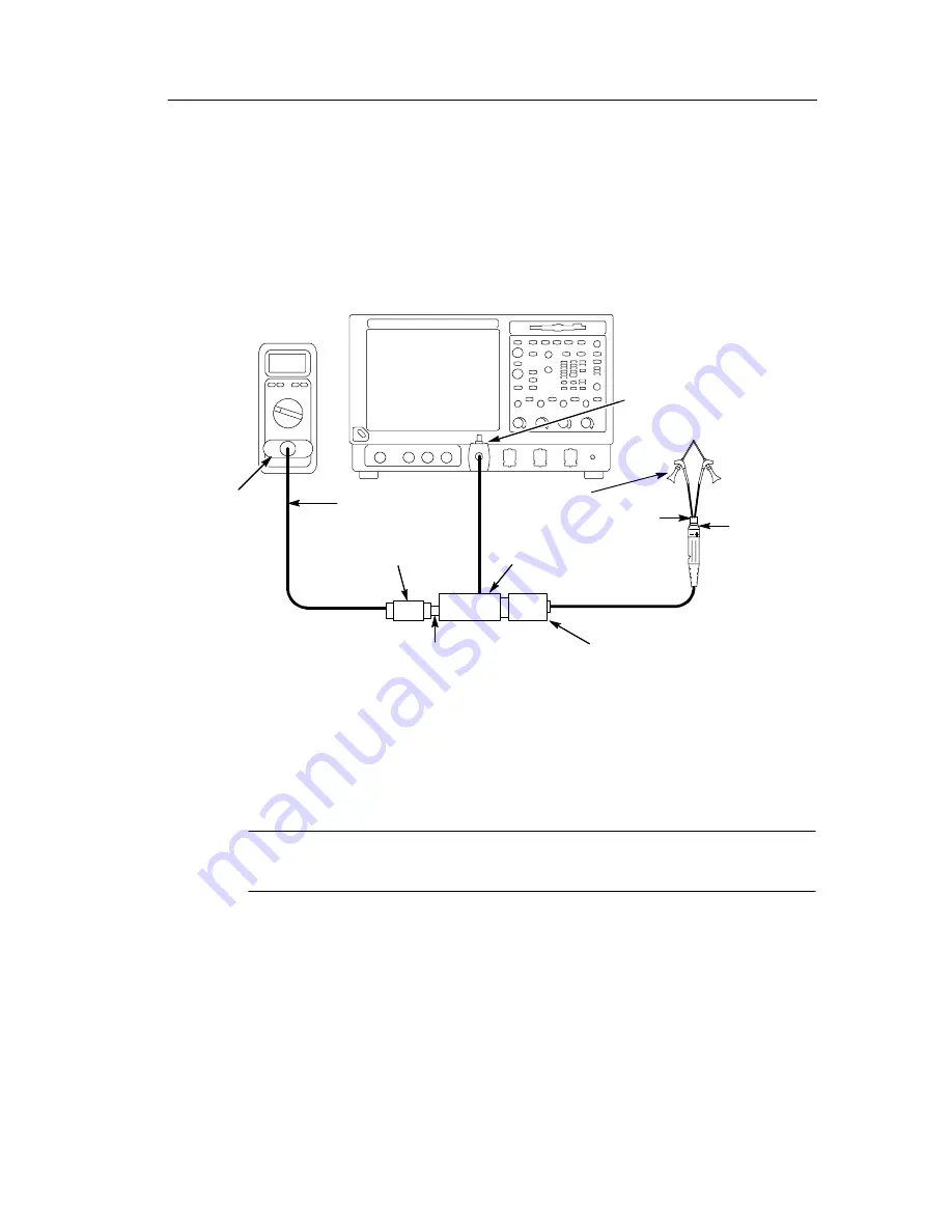
Connect the equipment as shown in Figure 21.
TDS7404 Oscilloscope
BNC-to-Dual
Banana adapter
50
Ω
Precision
termination
Digital
multimeter
Set offset switch
to GND
BNC-SMA adapter
Calibration
adapter
P7350 Probe
BNC Cable
Y-lead
adapter
KlipChip
adapters
Square
pin
adapter
Figure 21: Setup for the output offset voltage test
2.
Set the offset switch on the calibration adapter to
GND
.
NOTE
. Leave the offset switch in the ground position for all of the
performance verification checks.
3.
Set the multimeter to read DC volts.
4.
Verify that the output voltage is 0 V,
±
10 mV.
5.
Record the results on the test record.
Содержание 071-1238-00
Страница 4: ......
Страница 12: ...Service Safety Summary viii P7350 5 GHz Differential Probe Instruction Manual ...
Страница 22: ...Getting Started 10 P7350 5 GHz Differential Probe Instruction Manual ...
Страница 66: ...Appendix D Replaceable Parts P7350 5 GHz Differential Probe Instruction Manual 54 ...


