background image


of 

12 

© 

2008     W 

544 

12/08

W 544

12/08

tekmarNet

®

4 Thermostat 544

- Wiring Brochure

Overview

Information 

Brochure

Choose controls

to match

application

1

Application 

Brochure

Design your 

mechanical 

applications

2

Layout

Brochure

Rough-in

wiring 

instructions

3

Wiring

Brochure

Wiring and 

installation of 

specific control

4

Job

Record

Record settings & 

wiring details for 

future reference

6

Data

Brochure

Control settings 

and sequence of 

operation

5

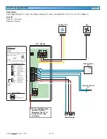
The following brochure describes how to wire the tekmar tekmarNet

®

4 (tN4) thermostat 544. The 544 has outputs for:

one heat stage, one cooling stage and one fan. The 544 has inputs for two auxiliary sensors. The wiring of 544 thermostat 
is simple and cost effective.

Table of Contents:

Definitions .......................................................................2
Rough-In Wiring  .............................................................2
Remove the Wiring Cover  ..............................................3
Mounting the Thermostat  ...............................................3
Wiring Symbols ...............................................................3

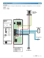
Electrical Drawings ......................................................3-7
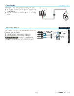
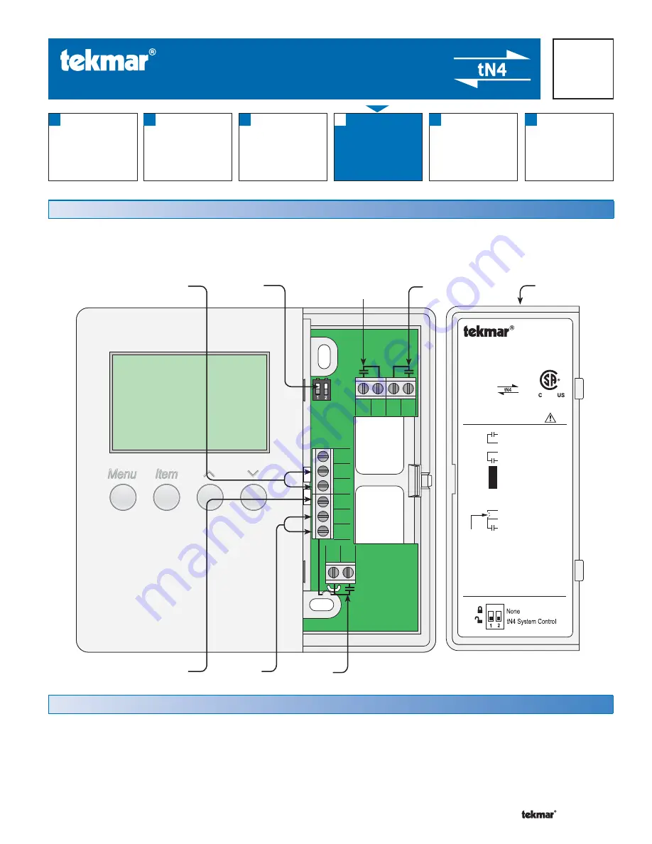
Wiring the Thermostat .................................................8-9
Troubleshooting the Wiring ........................................... 10

Testing the Wiring ......................................................... 11

Technical Data .............................................................. 12

tNt 544

One Stage Heat, One Stage Cool, One Fan


Power:  24 V (ac) ±10% 60 Hz 1.5 VA
Relays: 24 V (ac) 2 A

G1

Rc
Y1
Com
S2
S1
tN4
C
R
Rh1
W1

Fan 1 Relay

G1

Fan 1 Relay
Power Cooling
Cool 1 Relay
Sensor Common
Sensor 2
Sensor 1
tekmarNet  4
Power Neutral
Power 24 V (ac)
Heat 1 Relay
Heat 1 Relay

DIP Switch Functions

992-03


Meets Class B: Canadian ICES, FCC Part 15 

®

 
No Power

To isolate

relay, cut

jumper

Terminal Functions

Y1 Rc G1 G1

R

C

tN4

S1

S2

Com

W1

Rh1

24 V (ac)

Power

tN4

Network

1st Stage

Cooling

1st Stage

Heating

DIP

Switches

Auxiliary

Sensors

1st Stage

Fan

Wiring
Cover

Содержание tekmarNet 4 544

Страница 1: ...ng of 544 thermostat is simple and cost effective Table of Contents Definitions 2 Rough In Wiring 2 Remove the Wiring Cover 3 Mounting the Thermostat 3 Wiring Symbols 3 Electrical Drawings 3 7 Wiring the Thermostat 8 9 Troubleshooting the Wiring 10 Testing the Wiring 11 Technical Data 12 tNt 544 One Stage Heat One Stage Cool One Fan Power 24 V ac 10 60 Hz 1 5 VA Relays 24 V ac 2 A G1 Rc Y1 Com S2 ...

Страница 2: ...on condensing environment No exposure to extreme temperatures beyond 32 122 F 0 50 C No draft direct sun or other cause for inaccurate temperature readings Rough In Wiring Sensor 2 Sensor 1 Fan 1 2 Cond 18 AWG 2 Cond 18 AWG 2 Cond 18 AWG 2 Cond 18 AWG 4 Cond 18 AWG 1st Stage Cool Note When multiple wires run to the same equipment location wiring conductors can share one wire jacket 1st Stage Heat ...

Страница 3: ... the system designer to Electrical Drawings OR Wiring Symbols Dry contact switch Operates a device Do not apply power to these terminals Serious control damage will result Powered switch 24V ac switched output to valve pump relay etc tekmarNet 4 Factory jumper If a switch box was not used mount the thermostat directly to the wall Feed the wiring through the openings in the back of the thermostat U...

Страница 4: ...witch Functions 992 03 Meets Class B Canadian ICES FCC Part 15 No Power To isolate relay cut jumper Terminal Functions 10 9 8 7 6 5 12 11 4 3 2 1 544 tNt Slab Sensor 079 tN4 C R W Zone Manager Factory installed jumper connects R to Rh1 terminals 11 to 12 To isolate Rh1 W1 relay cut jumper Cooling Equipment 1 Stage Cooling 1 Stage Fan Rc Y1 G1 Outdoor Sensor 070 Y1 Rc G1 Com S2 S1 tN4 C R Rh1 W1 G1...

Страница 5: ... 03 Meets Class B Canadian ICES FCC Part 15 No Power To isolate relay cut jumper Terminal Functions 10 9 8 7 6 5 12 11 4 3 2 1 544 tNt tN4 C R W Zone Manager Factory installed jumper connects R to Rh1 terminals 11 to 12 To isolate Rh1 W1 relay cut jumper Cooling Equipment Y1 Rc Com S2 S1 tN4 C R Rh1 W1 Rc Y1 G1 1 Stage Cooling with Fan Indoor Sensor 076 Ventilation Equipment G1 G1 G1 G1 Slab Senso...

Страница 6: ...elay G1 Fan 1 Relay Power Cooling Cool 1 Relay Sensor Common Sensor 2 Sensor 1 tekmarNet 4 Power Neutral Power 24 V ac Heat 1 Relay Heat 1 Relay DIP Switch Functions 992 03 Meets Class B Canadian ICES FCC Part 15 No Power To isolate relay cut jumper Terminal Functions 10 9 8 7 6 5 12 11 4 3 2 1 544 tNt tN4 C R W Zone Manager Factory installed jumper connects R to Rh1 terminals 11 to 12 To isolate ...

Страница 7: ...s 992 03 Meets Class B Canadian ICES FCC Part 15 No Power To isolate relay cut jumper Terminal Functions 10 9 8 7 6 5 12 11 4 3 2 1 544 tNt Factory installed jumper connects R to Rh1 terminals 11 to 12 To isolate Rh1 W1 relay cut jumper HVAC Equipment Y1 G1 Com S2 S1 tN4 R G1 1 Stage Heat 1 Stage Cooling 1 Stage Fan R C Y1 W G1 tN4 C Other tN4 Thermostat C Outdoor Sensor 070 Universal Sensor 071 R...

Страница 8: ... to R When the factory jumper is cut Rh1 W1 is an isolated switch No power is available from these terminals Heat 1 Relay Terminals 11 12 Wire 24V ac to terminals C and R If a Zone Manager is used Connect C on the thermostat to C on the proper zone of the Zone Manager Connect R on the thermostat to R on the proper zone of the Zone Manager If a 24V ac transformer is used Connect C on the thermostat...

Страница 9: ...2 3 Thermostat The auxiliary sensors are connected to the thermostat on terminals Com S1 and S2 Connect sensor 1 to terminals S1 and Com Connect sensor 2 to terminals S2 and Com Do not apply power to terminals 5 7 permanent damage to the sensors and or thermostat will result Auxiliary Sensors Terminals 5 7 Do Not Apply Power Thermostat Universal Sensor Outdoor Sensor To various tekmar sensors 3 2 ...

Страница 10: ...rocedures and should only be carried out by properly trained and experienced persons A good quality electrical test meter capable of reading from at least 0 300V ac 0 2 000 000 Ohms and testing for continuity is essential to properly test the wiring and sensors General 5 Com 6 S2 7 S1 8 tN4 9 C 10 R Rh1 W1 11 12 4 3 2 1 Y1 Rc G1 G1 ...

Страница 11: ...e Relays To test the sensors the actual temperature at each sensor location must be measured Use a good quality digital thermometer with a surface temperature probe for ease of use and accuracy Where a digital thermometer is not available place a spare sensor alongside the one to be tested and compare the readings Testing the Sensors 1 Remove the front cover from the thermostat 2 Disconnect the wi...

Страница 12: ...II Pollution Degree 2 Power supply 24V ac 10 60 Hz 1 5 VA NEC CEC Class 2 W1 Relay 24V ac 2 A Y1 Relay 24V ac 2 A G1 Relay 24V ac 2 A Sensors NTC thermistor 10 k 77 F 25 C 0 2 C ß 3892 Included None Optional tekmar type 070 071 072 073 076 077 078 079 082 084 Technical Data The installer must ensure that this control and its wiring are isolated and or shielded from strong sources of electromag net...

Отзывы: