5
of
12
©
2008 W
544
-
12/08
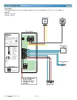
Electrical Application
544 E2
tNt 544
One Stage Heat, One Stage Cool, One Fan
Power: 24 V (ac) ±10% 60 Hz 1.5 VA
Relays: 24 V (ac) 2 A
G1
Rc
Y1
Com
S2
S1
tN4
C
R
Rh1
W1
Fan 1 Relay
G1
Fan 1 Relay
Power Cooling
Cool 1 Relay
Sensor Common
Sensor 2
Sensor 1
tekmarNet 4
Power Neutral
Power 24 V (ac)
Heat 1 Relay
Heat 1 Relay
DIP Switch Functions
992-03
Meets Class B: Canadian ICES, FCC Part 15
®
No Power
To isolate
relay, cut
jumper
Terminal Functions
10
9
8
7
6
5
12
11
4
3
2
1
544 tNt
tN4
C
R
W
Zone Manager
Factory installed jumper
connects R to Rh1
(terminals 11 to 12) To
isolate Rh1-W1 relay,
cut jumper
Cooling Equipment
Y1 Rc
Com
S2
S1
tN4
C
R
Rh1 W1
Rc Y1 G1
1 Stage Cooling
with Fan
Indoor Sensor
076
Ventilation
Equipment
G1 G1
G1 G1
Slab Sensor
079
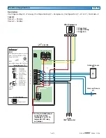
Description:
One Stage Heating (H1 = Radiant), One Stage Cooling (C1 = Compressor & Fan), One Ventilation Fan (F1 = Vent),
Fan Mode = None.
Legend:
Sensor 1 = Room
Sensor 2 = Floor


