background image

20

Gea-Top/001

UK

PL

ES


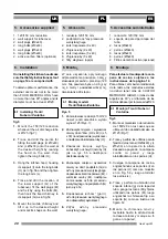
5. Akcesoria

1. redukcja 120/150 mm
2. podpórki do os³ony przewodu

wentylacyjnego

2. korki rozporowe (9 x 40)
2. d³ugie œruby (9 x 40)
6. korki rozporowe (5 x 40)
6. d³ugie œruby (5 x 40)
2. filtry wêglowe (opcja)

 6. Monta¿

W celu uzyskania optymalnego
odprowadzenia powietrza nale¿y
stosowaæ przewód o przekroju 120
mm. Nie powinien byæ on d³u¿szy
ni¿ 4 metry i posiadaæ wiêcej ni¿
dwa kolanka 90 stopni.


6.1 Monta¿ modeli:

Trenti/ Nubero/Ventoline

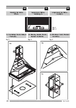
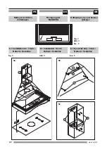
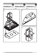
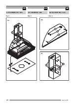
Rys. 5
1.

Zamontowaæ redukcjê 150/120
nawet jeœli œrednica wylotu
wynosi 125 (Rys. 7);

2.

Zaznaczyæ miejsca  i wywierciæ
otwory do ko³ków (H 9 x 40) i (L 5
x 30) na odpowiedniej wysokoœci
a nastêpnie dokrêciæ œruby (H);

3.

Zawiesiæ korpus wyci¹gu
zahaczaj¹c o uchwyt (I) œruby (H)
jak na rys. 5b a nastêpnie
dokrêciæ œruby (L);

4.

Zaznaczyæ miejsca i wywierciæ
otwory na doln¹ podpórkê (G) do
os³ony przewodu wentylacyjnego,
dopasowaæ korki rozporowe (M) i
wkrêciæ œruby (M), nastêpnie
zamocowaæ os³onê przewodu
wentylacyjnego na podpórkach (G)
jak na rys. 5c;

5.

Dopasowaæ ruchom¹ (górn¹)
os³onê przewodu wentylacyjnego
do odpowiedniej wysokoœci;

6.

Zdj¹æ os³ony przewodu
wentylacyjnego;


5. Accessories supplied

1. 120/150 mm reduction
2. wall support for tubecover
2. wall plugs (Ø9x40)
2. long bolts (Ø9x40)
6. wall plugs (Ø5x40)
6. long bolts (Ø5x40)
2. active carbon filters (optional)

 6. Installation

On installing the kitchen hood make
sure thet Safety Instructions set out
on page 14 are complied with.

To obtain optimum performance, the
external duct must not to be more
than FOUR METERS LONG, have
no more than two 90° angles and its
diameter must be at least Ø120.

 6.1 Installing: Trenti /

Nubero / Ventoline

fig.5
1.

Mount the 150/120 reduction
whenever the air discharge tube
is Ø125 (fig.7);

2.

Trace and drill the points for
fitting the wall plugs (H Ø9x40)
and (L Ø5x30) onto the wall at
the desired height by leaning
the hood on the wall, then
tighten the long bolts (H);

3.

Hang the kitchen hood, hooking
its support (I) onto the long bolts
(H) as in fig.5b and then tighten
the long bolts (L);

4.

Trace and drill the location of
the lower support (G) of the
tubecover, fit the wall plugs (M)
and fix it by using the bolts (M),
then hook the fixed chimney to
its support (G) as in fig.5c;

5.

Mount the mobile chimney and
lift it up to the desired height
and mark its shape on the wall;

 5. Accesorios suministrados

1. reducción 120/150 mm
2. soporte de pared para tapa del

tubo

2. tacos (Ø9x40)
2. pernos (Ø9x40)
6. tacos (Ø5x40)
6. pernos (Ø5x40)
2. Filtros de carbón activo (opcional)


6. Montaje

Para efectuar el montaje de la cam-
pana de cocina, sujétese a las
instrucciones de la página 14.

Para obtener el máximo rendimiento
de la misma, los conductos externos
no deben tener más de CUATRO
METROS DE LARGO, ni más de dos
ángulos de 90 °y el diámetro de los
mismos debe ser por lo menos de Ø120.

  6.1 Montaje: Trenti / Nubero /

Ventoline

fig.5
1.

Monte el mecanismo de reducción
de 150/120 en los casos que se
utilice un tubo de salida del aire  de
Ø125 (Fig.7);

2.

Trace y perfore los orificios para la
fijación de los tacos ((H Ø9x40) y (L
Ø5x30) en la pared a la altura
deseada apoyando la campana
contra la pared y luego
atornillándola con los pernos (H);

3.

Cuelgue la campana de cocina,
enganchando sus soportes (I) en
los pernos (H) como se muestra
en la Fig. 5b y luego atornillar
los pernos (L);

4.

Trace y perfore la ubicación del
soporte inferior (g) de la tapa del
tubo, ponga los tacos (M) y fíjelos
utilizando los pernos (M), luego
enganchar la chimenea fija a su
soporte (G) como se ilustra en la
figura Fx;

5.

Monte la chimenea móvil y
levántela hasta la altura donde
la desea colocar y marque su fi-
gura en la pared;

Содержание LARO 90

Страница 1: ...0 90 NUBERO 60 90 Instrukcja obs ugi i monta u Wyci g kuchenny LARO 90 TRENTI 90 VENTOLINE 60 90 NUBERO 60 90 UK PL ES FR DE GR Manual de Instrucciones Campana de cocina Gebrauchsanwei sung Dunstabzugshauben Notice d utilisation Hottes de cuisine Åã åéñßäéï ïäçãéþí ÁðïññïöçôÞñáò êïõæßíáò ...

Страница 2: ...liance must be connected to the network using a break switch with a universal cut off and minimum contact separation of 3 mm Once the kitchen hood has been installed ensure that the mains cable to the network is not in contact with any live metal edges Avoid connecting the appliance to conductors used as exits for fumes produced by a non electric energy source e g boilers chimneys etc If the extra...

Страница 3: ...ant aux ac cessoiresélectriquesàusagedomesti que et à l évacuation du gaz S assurer que la tension et que la fré quence de réseau correspondent par faitement à celles mentionnées sur l étiquette autocollante située à l inté rieur de la hotte Pour brancher cet appareil au réseau utiliser un interrupteur avec rupteur universel et une distance minimale de contact de 3 mm Une fois la hotte installée s...

Страница 4: ...cleaning the kitchen hood s interior Your kitchen hood is designed for domestic use and only for extraction and purification of fumes produced during food preparation It will be your responsibility if it is used for other purposes which may be dangerous The manufacturer cannot accept responsibility for damage caused by improper use of the appliance For repairs please contact the nearest TEKA Techn...

Страница 5: ...ppareil avant d interve nir à l intérieur de la hotte c est à dire pendant le nettoyage ou l entretien Il est recommandé d utiliser des gants et de faire très attention lorsque vous nettoyez l intérieur de la hotte de cui sine Votre hotte de cuisine a été spécifique ment conçue pour un usage domesti que et uniquement pour évacuer et purifier des émanations de fumées ré sultantdelacuissondesaliment...

Страница 6: ...uctions 2 1 Description of the appliance 6 2 Instructions for use 8 3 Cleaning and maintenance10 3 1 Cleaning the hood body10 3 2 Problem solving 10 3 3 Changing the light bulbs 10 4 Size and specifications 14 4 1 Technical specifications 14 4 2 Dimensions 14 5 Accessories supplied 18 6 Installation 18 6 1 Installing Trenti Nubero Ventoline 18 6 2 Installing Laro 20 7 Active carbon filters optiona...

Страница 7: ... F Partie décorative TABLE DES MATIÈRES Page Consignes de sécurité 3 1 Description de l appareil 7 2 Mode d emploi 9 3 Nettoyage et entretien 11 3 1 Nettoyage du corps de la hotte 11 3 2 Dépannage 11 3 3 Substitution des ampoules 11 4 Dimensions et spécifications 15 4 1 Caractéristiques techniques 15 4 2 Dimensions 15 5 Accessoires fournis 19 6 Installation 19 6 1 Installation de Trenti Nubero Ven...

Страница 8: ...ctor fan to run for several minutes after you have finished cooking between 3 to 5 minutes in order to expel all the grease from the outlet duct This prevents the return of grease smoke and smells 2 Instructions for use fig 2 You may control the kitchen hood by operating the controls as shown in the diagram Off Minimum speed Medium speed Maximum speed Light On Light Off Fig 2 Encienda el extractor...

Страница 9: ... core quelques minutes entre 3 et 5 minutes après l extinction des feux arrêt de la cuisson pour faire sortir toute la graisse du conduit d éva cuation Cela permettra d éviter un refoulement de graisse de fumée ou de mauvaises odeurs 2 Mode d emploi fig 2 Pour contrôler la hotte de cuisine effectuer les vérifications indiquées dans l illustration ci contre OFFArrêt Vitesseminimum Vitessemoyenne Vi...

Страница 10: ...the tap or using special anti grease products They can also be washed in a dishwasher In this case it is advisable to stack them vertically to avoid food residues to stick to them Cleaning in a dishwasher with ag gressive detergents or polish may damage the metallic surface blackening it although this will not affect its fat retention capacity Once clean leave them to dry off and then fit them ont...

Страница 11: ...s le robinet ou utiliser des produits antigraisse spé cifiques Les filtres peuvent aussi être lavés dans un lave vaisselle Dans ce cas il est recommandé de les placer ver ticalement dans le lave vaisselle pour éviter que des dépôts de nour riture ne restent collés Le nettoyage en lave vaisselle avec des produits détergents ou lustrants polish agressifs est susceptible d en dommager les surfaces mé...

Страница 12: ...the network There is no current in the network Filters are satured with fat Obstruction in the air conduct The lamps are blown The lamps are slack Solution Connect mains cable to the network Provide current to the network Change or clean the active charcoal and or metal filters as the case may be Remove the obstruction Change the lamps Tighten the lamps Problema El extractor no funciona La campana...

Страница 13: ... s allument pas Cause probable Lecâbleprincipaln estpasbran ché au réseau d alimentation Il n y a pas de courant dans le réseau Les filtres à graisse sont satu rés Le conduit d aération est bou ché Les ampoules ont grillé Les ampoules sont trop fai bles dévissées Solution au problème Brancher le câble principal au réseau d alimentation Rétablir le courant Changer ou nettoyer les fil tres à charbon...

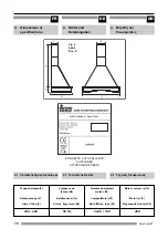
Страница 14: ...IQUETA ADHESIVA 4 Sizes and specifications 4 1 Technical specifications 4 Tamaño y especificaciones ELECT 230 240 V 50 Hz 210 W Network frequency Hz Czêstotliwoœæ Hz Red frecuencia Hz 50 Hz Lights Motor Power W Oœwietlenie Moc silników W Luces Motor Potencia W 2x40 130 Motor Volume m3 h Wydajnoœæ m3 h Motor Volumen m3 h 480 Fig 4 Rys 4 4 1 Especificaciones técnicas ...

Страница 15: ...1 Ôå íéêÝò äéåõêñéíßóåéò ETIQUETTE AUTOCOLLANTE AUFKLEBER ÁÕÔÏÊ ËËÇÔÇÅÔÉÊÅÔÁ ELECT 230 240 V 50 Hz 210 W Fig 4 Abb 4 Åéê 4 Tensionderéseau V Netzspannung V Äßêôõï ÔÜóç V 230 240 Frequence de réseau Hz Netzfrequenz Hz Äßêôõï Óõ íüôçôá Hz 50 Hz Puissance Ampoules moteur W Lampen Motor W Öþôá ÌïôÝñ Éó ý W 2x40 130 Moteur volume m3 h Motor m3 h Ìç Üíçìá Åíôáóç m3 h 480 ...

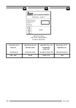
Страница 16: ...etwork frequency Hz Czêstotliwoœæ Hz Red frecuencia Hz 50 Hz Lights Motor Power W Oœwietlenie Moc silników W Luces Motor Potencia W 2x40 315 Motor Volume m3 h Wydajnoœæ m3 h Motor Volumen m3 h 780 ELECT 230 240 V 50 Hz 395 W ADHESIVE LABEL TABLICZKA ZNAMIONOWA ETIQUETA ADHESIVA ...

Страница 17: ...0 240 Frequence de réseau Hz Netzfrequenz Hz Äßêôõï Óõ íüôçôá Hz 50 Hz Puissance Ampoules moteur W Lampen Motor W Öþôá ÌïôÝñ Éó ý W 2x40 315 Moteur volume m3 h Motor m3 h Ìç Üíçìá Åíôáóç m3 h 780 ELECT 230 240 V 50 Hz 395 W ETIQUETTE AUTOCOLLANTE AUFKLEBER ÁÕÔÏÊ ËËÇÔÇÅÔÉÊÅÔÁ ...

Страница 18: ... B mm C mm D mm E mm F mm MIN MAX VENTOLINE 60 600 502 488 988 122 157 218 VENTOLINE 90 900 502 494 994 122 157 218 PAINTED STEEL MODEL PINTADO ACERO PAINTED STEEL MODEL PINTADO ACERO TEKA INDUSTRIAL S A se reserva el derecho de introducir cambios y modificaciones que considere necesarios en sus productos sin al terar sus características básicas 4 2 Wymiary Rys 4 4 2 Dimensions Fig 4 A mm B mm C m...

Страница 19: ...C mm D mm E mm F mm MIN MAX VENTOLINE 60 600 502 488 988 122 157 218 VENTOLINE 90 900 502 494 994 122 157 218 ACIER VERNI FARBIG STAHL ÂÁÌÌÅÍÏ ÁÔÓÁËÉ ACIER VERNI FARBIG STAHL ÂÁÌÌÅÍÏ ÁÔÓÁËÉ TEKA INDUSTRIAL S A êáôÝ åé ôï äéêáßùìá íá êÜíåé áëëáãÝò êáé äéïñèþóåéò óôá ðñïéüíôá ôçò üôáí ôï èåùñåß áíáãêáßï äß ùò íá áëëÜæåé ôá âáóéêÜ ôïõò áñáêôçñéóôéêÜ 4 2 Maße Abb 4 4 2 Dimensions Fig 4 A mm B mm C mm ...

Страница 20: ...be is Ø125 fig 7 2 Trace and drill the points for fitting the wall plugs H Ø9x40 and L Ø5x30 onto the wall at the desired height by leaning the hood on the wall then tighten the long bolts H 3 Hang the kitchen hood hooking its support I onto the long bolts H as in fig 5b and then tighten the long bolts L 4 Trace and drill the location of the lower support G of the tubecover fit the wall plugs M an...

Страница 21: ...20 mm 6 1 Installation de Trenti Nubero Ventoline fig 5 1 Monter une réduction de 150 120 mm si le tuyau d évacuation de l air a un diamètre de 125 mm fig 7 2 Tracer puis percer dans le mur à la hauteur voulue les trous pour installer les prises murales H Ø9x40 et L Ø5x30 adosser la hotte contre le mur Serrer ensuite les écrous longs H 3 Maintenir suspendue la hotte de cuisine fixer son support I ...

Страница 22: ...Mount the 150 120 reduction whenever the air discharge tube is Ø125 fig 7 2 Trace and drill the points for fitting the wall plugs H Ø9x40 and L Ø5x30 onto the wall at the desired height by leaning the hood on the wall then tighten the long bolts H 3 Hang the kitchen hood hooking holes I onto the long bolts H as in fig 6b and then tighten the long bolts L 4 Trace and drill the location of the lower...

Страница 23: ...port G comme dans la figure 6c 10 Relier le tuyau de récupération au conduit extérieur le fixer au moyen d un collier de serrage 6 2 Installation de Laro fig 6 1 Monter une réduction de 150 120 mm si le tuyau d évacua tion de l air a un diamètre de 125 mm fig 7 2 Tracer puis perforer sur le mur à la hauteur voulue les trous où installer par la suite les prises murales H Ø9x40 et L Ø5x30 adosser la...

Страница 24: ...n filters The active carbon filters have an active life of between three to six months depending on the individual conditions of use These filters cannot be washed nor regenerated They must be replaced once their useful life comes to an end How to set active carbon filters 1 Put the filters into the lateral draught section of the motor through the holes presents on each filter and the pivots of th...

Страница 25: ...mobile autour de la bouche de sortie du ventilateur puis les fixer aux supports correspondants 10 Relier le tuyau de récupération au conduit extérieur le fixer au moyen d un collier de serrage 7 Filtres à charbon actif en option fig 8 Lorsque l évacuation du gaz vers l ex térieur n est pas possible la hotte de cuisine sera installée pour puri fier l air en le recyclant à travers des filtres à char...

Страница 26: ...e filtrów metalowych Fig 3 Rys 3 6 1 Monta modeli Trenti Nubero Ventoline Rys 5 5a 5b 5c Cleaning the metal filters 6 1 Installing Trenti Nubero Ventoline fig 5 Limpieza de los filtros metálico 6 1 Montaje Trenti Nubero Ventoline fig 5 ...

Страница 27: ...llfilter Fig 3 Abb 3 Åéê 5 6 1 Installation Trenti Nubero Ventoline Abb 5 Nettoyer les filtres métalliques 6 1 Installation de Trenti Nubero Ventoline fig 5 Êáèáñéóìüò ôùí ìåôáëéêþí ößëôñùí 6 1 ÅãêáôÜóôáóç Trenti Nubero Ventoline Åéê 5 5a 5b 5c ...

Страница 28: ...28 Gea Top 001 UK PL ES 6 2 Monta modelu Laro Rys 6 6a 6b 6c 6 2 Installing Laro fig 6 6 2 Montaje Laro fig 6 ...

Страница 29: ...FR DE GR 29 Gea Top 001 6 2 Installation Laro Rys 6 6 2 Installation de Laro fig 6 6 2 ÅãêáôÜóôáóç Laro Åéê 6 6a 6b 6c ...

Страница 30: ...ltry z wêgla aktywnego Rys 8 PL Active charcoal filters Fig 8 Monta przewodu wentylacyjnego Rys 7 How to assemble the out door scavenging pipe Fig 7 Filtros de carbón activo Fig 8 Cómo ensamblar el tubo de barrido externo Fig 7 ...

Страница 31: ... Abb 8 PL filtres à charbon actif Fig 8 Anbringen des Außen Abzugsschlauchs Abb 7 Comment monter le tuyau de récupération extérieur Fig 7 ÅíåñãïðïéÞóôå ôá ößëôñá ôïõ Üíèñáêá Åéê 8 Ðùò èá óõíáñìïëïãÞóåôå ôïí åîùåñôéêü óùëÞíá êáèáñéóìïý Åéê 7 ...

Страница 32: ...32 Gea Top 001 UK PL ES ...

Страница 33: ...K MALAYSIA SDN BHD TEKA MEXICANA S A DE C V TEKA POLSKA SP ZO O TEKA PORTUGUESA LTDA TEKA RUS LLC TEKA SINGAPORE PTE LTD TEKA THAILAND CO LTD TEKA B V TEKA TEKNIK MUTFAK A S TEKA PRODUCTS UK LTD TEKA USA INC TEKA ANDINA S A 43 32 56 86 42 33 30 36 62 60 52 48 351 7 65 66 31 90 44 1 58 1 86680 0 2466 8740 2 273 19 45 21 6236 2375 05 4921 0478 1 5836 4830 210 9760283 1 354 21 10 21 39052 74 3 762 01...

Страница 34: ...34 Gea Top 001 UK PL ES ...

Страница 35: ...FR DE GR 35 Gea Top 001 ...

Страница 36: ...EKA Industrial S A Cajo 17 39011 Santander Spain Tel 34 942 354 50 50 Faxl 34 942 34 76 94 www teka net TEKA Kuchentechnik GmbH Sechsheldner Str 122 35708 Haiger Germany Tel 49 2771 8141 0 Fax 49 2771 8141 10 www teka net 05 06 ...

Отзывы: