background image

28

REGLAGES

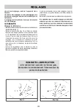
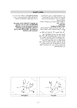
FIG. 13/A

FIG. 13

Avant  tout  réglage,  mettez  l’appareil  hors
tension.
Au  terme  des  réglages  ou  des  préréglages,  les
éventuels  scellages  doivent  être  rétablis  par  le
technicien.
Le réglage de l’air primaire n’est pas nécessaire
sur nos brûleurs.

9) ROBINETS

Réglage du «Minimum»:

- allumez le brûleur et tournez le bouton sur le Minimum

(petite flamme fig. 1).

- retirer  le  bouton  «M»  (fig.  13  et  13/A)  du  robinet

fixé par une simple pression sur le pivot de celui-
ci. Le régulateur de la capacité minimale peut se
trouver:  sur  le  côté  du  robinet  (fig.  13)  ou  à
l’intérieur  du  pivot.  En  tous  les  cas,  pour  le
réglage,  on  y  accède  en  insérant  un  petit
tournevis  «D»  sur  le  côté  du  robinet  (fig.  13),  ou
dan  le  trou  «C»  à  l’intérieur  du  pivot  du  robinet
(fig. 13/A).

- tourner  le  régulateur  vers  la  droite  ou  vers  la

gauche en réglant de façon appropriée la flamme
dans la position de capacité réduite.  

Il  est  recommandé  de  ne  pas  exagérer  avec  le
«Minimum»:  la  petite  flamme  doit  être  stable  et
constante. 
Remonter correctement les différents composants.

On  rappelle  que  le  susdit  réglage  ne  doit  être
effectué  qu’avec  les  brûleurs  fonctionnant  au
G20,  tandis  qu’avec  les  brûleurs  fonctionnant
au G30 ou au G31 la vis doit être bloquée à fond
(en sens horaire).

ROBINETS LUBRIFICATION

si le robinet est coincée ne forcez pas,

demander immédiatement l'intervention du

personnel autorisé.

Содержание EW 90 5G AI AL TR CI E1-ME

Страница 1: ... 60 4G AI AL CI E1 ME EWF 90 5G AI AL TR CI E1 ME EW 90 5G AI AL TR CI E1 ME COD 04071HG 04071ING 14 02 2019 These instructions are only valid if the country symbol appears on the appliance If the symbol does not appear on the appliance it is necessary to refer to the technical instructions which will provide the necessary instructions concerning modification of the appliance to the conditions of ...

Страница 2: ...ry gas burner of 1000 W 6 Enamelled steel pan support ultra rapid gas burner 7 Enamelled steel pan support 2F 8 Burner n 1 control knob 9 Burner n 2 control knob 10 Burner n 3 control knob 11 Burner n 4 control knob 12 Burner n 5 control knob Attention this appliance has been manufactured for domestic use only and it employment by private person This cook top was designed to be used exclusively as...

Страница 3: ...t again HOW TO USE THE BURNERS Bear in mind the following indications in order to achieve maximum efficiency with the least possible gas consumption use adequate pans for each burner consult the following table and fig 2 When the pan comes to the boil set the knob to the reduced rate position small flame fig 1 Always place a lid on the pans Use only pan with a flat bottom WARNINGS matches can be u...

Страница 4: ...to use this appliance any more or replace an old model before disposing of it make it inoperative in conformity with current law on the protection of health and the prevention of environmental pollution by making its dangerous parts harmless especially for children who might play on an abandoned appliance Do not touch the appliance with wet or damp hands or feet Do not use the appliance barefoot T...

Страница 5: ...rs Do not allow vinegar coffee milk salted water lemon or tomato juice from remaining in contact with the enamelled surfaces for long periods of time WARNINGS comply with the following instructions before remounting the parts check that burner head T fig 6 B slots have not become clogged by foreign bodies Check that enamelled burner cap A B C fig 6 A 6 B have correctly positioned on the burner hea...

Страница 6: ...3 and is therefore subject to all the provisions established by the provisions governing such appliances 4 FIXING THE HOT PLATE The hot plate has a special seal in the case of filotop or putty in the case of semifilo which prevents liquid from getting into the cabinet Strictly comply with the following instructions in order to correctly apply this seal detach the seals or putty from their backing ...

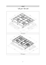
Страница 7: ...7 COMPLY WITH THE DIMENSIONS in mm INSTALLATION A B C D E 4F 565 495 52 5 52 5 60 min 5F 835 495 52 5 52 5 60 min ...

Страница 8: ...8 INSTALLATION FILOTOP HOT PLATE INSTALLATION 565 495 65 590 520 R 14 R 14 5 521 591 3 3 FIG 10 A 65 3 3 FIG 10 B ...

Страница 9: ...9 INSTALLATION SEMIFILO HOT PLATE INSTALLATION FIG 11 A FIG 11 B ...

Страница 10: ... an electric fan can be installed on a window or on a wall facing outside see fig 4 This must be activated at the same time as the appliance see fig 5 so long as the specifications in the provisions in force are strictly complied with 7 GAS CONNECTION Before connecting the appliance check that the values on the data label affixed to the underside of the hot plate correspond to those of the gas and...

Страница 11: ... main install an omnipolar circuit breaker between the appliance and the electricity main This circuit breaker should be sized according to the load rating of the appliance and possess a minimum 3 mm gap between its contacts Remember that the earth wire must not be interrupted by the circuit breaker The electrical connection may also be protected by a high sensitivity differential circuit breaker ...

Страница 12: ...o access to regulation it can be done trought the insertion of a small screwdriver D beside the tap fig 13 or in the hole C inside the shaft of the tap fig 13 A Turn the throttle screw to the right or left until the burner flame has been adequately regulated to the Reduced rate position The flame should not be too low the lowest small flame should be continuous and steady Re assemble the several c...

Страница 13: ...convenience the nominal rate table also lists the heat inputs of the burners the diameter of the injectors and the working pressures of the various types of gas BURNER ARRANGEMENT ON THE HOT PLATE FIG 14 TABLE BURNERS GAS NORMAL PRESSURE mbar NORMAL RATE INJECTOR DIAMETER 1 100 mm NOMINAL HEAT INPUT W N DESCRIPTION gr h l h Min Max 1 ULTRA RAPID G 30 BUTANE G 31 PROPANE G 20 NATURAL 28 30 37 20 22...

Страница 14: ...ct tightness Greasing the taps see fig 19 If a tap becomes stiff to operate it must be immediately greased in compliance with the following instructions remove the tap Clean the cone and its housing using a cloth soaked in diluent Lightly spread the cone with the relative grease Fit the cone back in place operate it several times and then remove it again Eliminate any excess grease and check that ...

Страница 15: ...ith the recommendations given in paragraph 8 SERVICING FIG 20 TYPE OF HOT PLATE TYPE OF CABLE SINGLE PHASE POWER SUPPLY Gas hot plate H05 RR F Section 3 x 0 75 mm2 In case of failure or cut in the cable please move away from the cable and do not touch it Moreover the device must be unplugged and not switched on Call the nearest authorized service center to fix the problem ...

Страница 16: ...Any repairs or adjustments which may be subsequently required may only be carried out by qualified personnel with the utmost care and attention For this reason always contact your Dealer or our nearest After Sales Service Center whenever repairs or adjustments are required specifying the type of fault and the model of the appliance in your possession Please also note that genuine spare parts are o...

Страница 17: ...AI AL CI E1 ME EWF 90 5G AI AL TR CI E1 ME EW 90 5G AI AL TR CI E1 ME COD 04071HG 04071FR 14 02 2019 Ces instructions sont seulement valides si le symbole de pays apparaît sur l appareil Si le symbole n apparaît pas sur l appareil il est nécessaire de se rapporter aux instructions techniques qui fourniront les instructions nécessaires au sujet de la modification de l appareil aux conditions de l u...

Страница 18: ...ommande du brûleur n 3 11 Bouton de commande du brûleur n 4 12 Bouton de commande du brûleur n 5 Attention cet appareil à été conçu pour l emploi domestique dans habitat domestiques et de part de sujets privés DESCRIPTION DES TABLES DE CUISSON MODÈLE EWF 60 4G AI AL CI E1 ME EW 60 4G AI AL CI E1 ME MODÈLE EWF 90 5G AI AL TR CI E1 ME EW 90 5G AI AL TR CI E1 ME Chaque plaque de cuisson a été conçue ...

Страница 19: ...ec une consommation minimale de gaz il est utile de rappeler les points suivants utiliser pour chaque brûleur des casseroles adéquates voir le tableau suivant et la fig 2 Lorsque l ébullition a été atteinte amener le bouton sur la position Minimum petite flamme fig 1 Toujours utiliser des casseroles avec un couvercle Utilisez seulement récipients avec fond plat AVERTISSEMENTS en cas de coupure de ...

Страница 20: ...de remplacer un ancien modèle avant de le porter à la démolition il est recommandé de le rendre inutilisable comme le prévoient les réglementations en vigueur en matière de protection de la santé et de pollution de l environnement Ne pas toucher l appareil avec les mains ou les pieds mouillés ou humides Ne pas utiliser l appareil avec les pieds nus Le fabricant ne peut être tenu pour responsable d...

Страница 21: ...re ni de sprays corrosifs Eviter que le vinaigre le café le lait l eau salée le jus de citron ou de tomate ne restent trop longtemps au contact des surfaces AVERTISSEMENTS lors du remontage des composants il est conseillé de s en tenir aux recommandations suivantes vérifier que les trous de sortie de gaz des répartiteurs de flamme T fig 6 B ne sont pas bouchés par des corps étrangers S assurer que...

Страница 22: ...outes les prescriptions prévues par les normes correspondantes 4 FIXATION DE LA TABLE DE CUISSON La table est équipée d une garniture spéciale dans le cas de filotop ou stuc dans le cas de filotop pour éviter toute infiltration de liquide dans le meuble Pour appliquer correctement cette garniture ou stuc prière de s en tenir scrupuleusement à ce qui est spécifié ci après détacher les bandes de la ...

Страница 23: ...23 DIMENSIONS A RESPECTER en mm INSTALLATION A B C D E 4F 565 495 52 5 52 5 60 min 5F 835 495 52 5 52 5 60 min ...

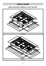
Страница 24: ...24 INSTALLATION INSTALLATION DE CUISSON OU GAZ FILOTOP 565 495 65 590 520 R 14 R 14 5 521 591 3 3 FIG 10 A 65 3 3 FIG 10 B ...

Страница 25: ...25 INSTALLATION INSTALLATION DE CUISSON OU GAZ SEMIFILO FIG 11 A FIG 11 B ...

Страница 26: ... la fenêtre ou sur le mur extérieur qu il faudra mettre en fonction simultanément à l appareil voir fig 5 à condition que les dispositions concernant la ventilation énumérées dans les normes en vigueur soient strictement respectées 7 RACCORDEMENT AU GAZ Avant de raccorder l appareil s assurer que les données figurant sur l étiquette signalétique appliquée sur la partie inférieure du caisson sont c...

Страница 27: ...près la fonction intégrée Lorsque le raccordement est directement réalisé sur le réseau électrique interposer entre l appareil et le réseau un interrupteur omnipolaire dimensionné à la charge de l appareil avec une ouverture minimale entre les contacts de 3 mm Ne pas oublier que le câble de mise à la terre ne doit pas être interrompu par l interrupteur Le réseau électrique peut également être prot...

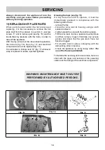
Страница 28: ...tous les cas pour le réglage on y accède en insérant un petit tournevis D sur le côté du robinet fig 13 ou dan le trou C à l intérieur du pivot du robinet fig 13 A tourner le régulateur vers la droite ou vers la gauche en réglant de façon appropriée la flamme dans la position de capacité réduite Il est recommandé de ne pas exagérer avec le Minimum la petite flamme doit être stable et constante Rem...

Страница 29: ...t les injecteurs correspondants au gaz utilisé Pour cela il est nécessaire d enlever les répartiteurs de flamme des brûleurs et au moyen d une clé droite B de dévisser l injecteur A voir fig 14 et de le remplacer par un injecteur correspondant au gaz utilisé Il est conseillé de bloquer énergiquement l injecteur Après avoir effectué les remplacements indiqués ci dessus le technicien devra procéder ...

Страница 30: ...le corps et la rampe Graissage des robinets voir fig 19 Si la manipulation d un robinet devient difficile il faut sans plus attendre le graisser en suivant les instructions ci après démonter le corps du robinet Nettoyer le cône et son logement au moyen d un chiffon imbibé de diluant Graisser légèrement le cône avec de la graisse spéciale Introduire le cône le bouger plusieurs fois l extraire à nou...

Страница 31: ... 4 FEUX G 30 BUTANE 28 30 mbar G 31 PROPANE 37 mbar G 20 NATUREL 20 mbar Qn Gaz Naturel 6 95 kW Qn GPL 505 gr h G30 496 gr h G31 TENSION 220 240 V FREQUENCE 50 60 Hz 5 FEUX G 30 BUTANE 28 30 mbar G 31 PROPANE 37 mbar G 20 NATUREL 20 mbar Qn Gaz Naturel 10 05 kW Qn GPL 731 gr h G30 718 gr h G31 TENSION 220 240 V FRECUENCE 50 60 Hz CARACTERISTIQUES TECHNIQUES REPORTEES SUR L ETIQUETTE SIGNALETIQUE E...

Страница 32: ...n que nous vous recommandons de toujours vous adresser au Concessionnaire qui a procédé à la vente ou à notre Centre d Assistance Technique le plus proche en spécifiant la marque le modèle le numéro de série et le type de défaut que présente votre appareil Les données correspondantes sont poinçonnées sur l étiquette signalétique appliquée sur la partie inférieure de votre appareil ainsi que sur l ...

Страница 33: ...صﻼحات أو تﻌدﻳﻼت كﻲ ﻳ ﺘﻢ توصيف نوع الﻌيﺐ حﺴﺐ المودﻳﻞ الﺘﻲ تمﺘلﻜﻪ كذلك ﻳرجﻲ ﻣﻼحﻈﺔ أن ﻗﻄع الغيار اﻻصليﺔ ﻣﺘوﻓرة ﻓقﻂ ﻣركﺰ الخدﻣﺔ المﻌﺘمد أو ﺑاﺋع الﺘجﺰﺋﺔ المواصفات المذكورة ﺳلفا تﻢ طﺒﻌها ﻋلﻲ لوحﺔ الﺒيانات الموجودة ﻋلﻲ الجﺰء الداخلﻲ للجهاز واﻳضا توجد ﻋلﻲ اﻻﺳﺘيﻜر الملﺼق ﺑالﻜرتو نﺔ المﻌلوﻣات الﺴاﺑقﺔ توﺿﺢ للفﻨﻲ المﺘخﺼﺺ كيفيﺔ الﺤﺼول ﻋلﻲ ﻗﻄع الغيار المﻨاﺳﺒﺔ و توﺿيﺢ الخلﻞ الفﻨﻲ لذا نقﺘرح ﻣﻸ الجدول الﺘالﻲ المار...

Страница 34: ...التوصيل سلك في قطع أو خلل وجود حالة في مﻼمسته للتعامل معتمد صيانة مركز بأقرب اﻻتصال و تشغيله وعدم الجهاز فصل يجب كما المشكلة مع ﻹﺳ التقنية المعلومات تيكﺮالﺒياﻧات 4 شعﻼت G30 بوتان 28 30 بار ملي G31 بروبان 37 بار ملي G20 طبيعي 20 بار مللي طبيعي غاز Qn 6 95 وات كيلو Qn GPL 505 س ج G30 496 س ج G31 الفولطية 220 240 فولط التردد 50 60 هرتز 5 شعﻼت G30 بوتان 28 30 بار ملي G31 بروبان 37 بار ملي G20 طبيعي 20...

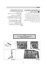
Страница 35: ... كل في التام اﻹحكام لضمان فيها الصنابير ﺗﺸح ي م ال صنابيﺮ اﻧظﺮ ال ﺸكل 19 ﻓﻲ حالﺔ وجود صﻌوﺑﺔ ﻓﻲ تﺤرﻳك المفاتيﺢ ﻳجﺐ تشﺤيمها ﻓﻲ الﺤال وﻓقا ل لخﻄوات الﺘاليﺔ ﻗﻢ ﺑفك المقﺒض نﻈف الﺴﻦ المخروطﻲ وﻣﻜان دخولﻪ ﺑقﻄﻌﺔ ﻗماش ﻣﺒللﺔ وزع الشﺤﻢ ﻋلﻲ ﺳﻦ المخروط اﻋد تركيﺐ الﺴﻦ ﻓﻲ ﻣﻜانﻪ وﻗﻢ ﺑﺘشغيلﻪ ﻋدة ﻣرات ﺛﻢ اخلﻌﻪ ﻣرة اخري وﻗﻢ ﺑإزالﺔ ﺑقاﻳا الشﺤﻢ الﺰاﺋدة وتاكد ﻣﻦ ﻋدم إنﺴداد أنﺒوب الغاز اﻋد تركيﺐ جميع اﻷجﺰاء ﻓ ﻲ ﻣﻜانها وﻓ...

Страница 36: ...لشعﻼت كما هو موﺿﺢ ﺑالفقرة 9 ي جب علﻰ الفني إعادة ﺿبﻂ أي جوانات علﻰ المنظمات أو أجهزة الضبﻂ المسبق الطرﺑوش علﻰ الشعﻼت ترتيب جدول الشعﻼت الغاز الضغط العادي بار مللي المعدل العادي قطر المحقن 1 100 مم مدخل الحرارة المبدئي وات N البيان ج س ل س اﻷدنى الحد الحد اﻷقصى 1 فائﻖ السرعة G30 بوتان G31 بروبان G20 طبيعي 28 30 37 20 225 221 295 90 90 Y 121 1800 1800 1800 3100 3100 3100 2 سريع G30 بوتان G31 بروبان ...

Страница 37: ...ﻗﻞ الضﺒﻂ وﺿع ﻳﻜون أن ﻳمﻜﻦ ﻗضيﺒﻪ الشﻜﻞ الﺼﻨﺒور ﺑجانﺐ 13 ﻓﻲ الﻌمود داخﻞ أو تﺼﻞ أن تﺴﺘﻄيع حﺘﻲ اﻷحوال جميع ﻣفﺘاح إلى صغير ﻣفك تدخﻞ أن ﻳمﻜﻨك الضﺒﻂ D ﺑجانﺐ الشﻜﻞ الﺼﻨﺒور 13 الفﺘﺤﺔ ﻓﻲ أو c ﻋمود داخﻞ الشﻜﻞ الﺼﻨﺒور 13 A إلى القاذف ﺑإدراة ﻗﻢ الشﻌلﺔ لهﺐ ﺿﺒﻂ ﻳﺘﻢ حﺘﻲ اليﺴار إلى أو اليميﻦ المخفض الوﺿع إلى يكون ﻻ أن يﺠﺐ ﻳجﺐ حيث جدا ﻣﻨخفضا اللهﺐ تﻜون أن ﻳرجى وﻣﺴﺘقرة ﻣﺴﺘمرة شﻌلﺔ أﻗﻞ الضﺒﻂ ﺑﻌد المخﺘلفﺔ المﻜونات تجم...

Страница 38: ...ﻳجﺐ تركيﺐ ﻣفﺘاح لفﺼﻞ الﺘيار ﺑيﻦ الجهاز نفﺴﻪ و الﺘيار الﻜهرﺑﻲ وهذا المفﺘاح ﻳجﺐ ان ﻳﻜون ﻣقاﺳﻪ ﻣﻄاﺑق لمﻌدل تﺤميﻞ الجهازﻣع الﺤفاظ ﻋلﻲ ﻣﺴاﻓﺔ ٣ ﻣﻢ ﻋلﻲ اﻷﻗﻞ ﺑيﻦ وص ﻼتﻪ تذكر أ ن الﻄرف اﻷرﺿﻲ ﻻ ﻳجﺐ ﻓﺼلﻪ ﻋﻦ تيار ﺑقاطع الداﺋرة ل مﺰﻳد ﻣﻦ الﺤماﻳﺔ لﻌمليﺔ الﺘوصيﻞ الﻜهرﺑﻲ ﻳمﻜ الﺤﺴاﺳيﺔ ﻋالﻲ داﺋرة ﻗاطع تركيﺐ ﻦ ﻳﻨﺼﺢ لفﻨﻲ الﺘركيﺐ أ ن ﻳقوم ﺑﺘوصيﻞ الﻄرف اﻷرﺿﻲ اﻷصفر و اﻻخضر ﻣﻨاﺳﺐ تأرﻳض ﺑﻨﻈام ﻋلى ﻋملية أية إجﺮاء ﻓى الﺸﺮوع...

Страница 39: ...ﻓذة الغرﻓﺔ ﻓﻲ ﺑالﺤاﺋﻂ المجاور للخار ج انﻈر ال شﻜﻞ ٤ ﻋلﻲ ان ﻳﺘﻢ تشغيلها أﺛﻨاء اﺳﺘخدام الجهاز انﻈر ال شﻜﻞ ٥ لذا ﻳجﺐ إتﺒاع المواصفات الخاصﺔ ﺑﻌمليﺔ الﺘركيﺐ ﺑشﻜﻞ صارم 7 ﺗوص ي ل الغاز قﺒل ﺗوص ي ل الﺠ ه از ﺗاكﺪ مﻦ ان القيم المﺬكورة ﻓﻲ اﺳت ي كﺮ ال ﺒ ي اﻧات المثﺒت بالﺠزء السفلﻲ للﺠ ه از مطابقة لمقاي ي ﺲ الغاز او الك ه ﺮباء الموجودة بمنزلك اﻻﺳت ي كﺮ الموجود بالﺠ ه از ي ﺸ ي ﺮ الﻲ معاي ي ﺮ النظام كنوع الغاز و...

Страница 40: ...9 التﺮكيﺐ تركيب موقد سيمي فيلو الشﻜﻞ 11 A الشﻜﻞ 11 B ...

Страница 41: ...8 التﺮكيﺐ تركيب موقد فيلوتوب الشﻜﻞ 10 A الشﻜﻞ 10 B ...

Страница 42: ...7 التﺮكيﺐ ا المقاييﺲ إﺗﺒاع يﺮجﻲ لتالية E D C B A 60 حد أدني 52 5 52 5 495 565 4F 60 حد أدني 52 5 52 5 495 835 5F ...

Страница 43: ...بطقة المفرز المسطح على فرش للنفاذية ينﺪرج ه ا ﺬا لﺠ ه از ﺗحت الفئة 3 ﻓ لﺬا ه و لكاﻓة يخضع اﻷحكام المقﺮرة التﻲ بالﺒنود ﺗحكم ﺗ اﻷجهزة لك 4 ﺗﺮك ي ﺐ السطح هذا الﺴﻄﺢ ﻣﺰود ﺑشرﻳﻂ ﻋازل وذلك وﻓﻲ طراز حالﺔ ﻓﻲ ﻣﻌجون أو توب الفيلو طراز حالﺔ ﻓيلو الﺴيمﻲ لمﻨع تﺴرب الﺴواﺋﻞ داخﻞ الﻜاﺑيﻨﺔ لذا ﻳجﺐ ﻣراﻋاة الﺘﻌليمات الﺘا ليﺔ للﺘأكد ﻣﻦ تركيﺐ الﻌازل ﺑشﻜﻞ صﺤيﺢ انزع العازل عبواتهم من المعجون أو وتأكد من أن جزء الح ملتصﻖ ...

Страница 44: ...و الﻄماطﻢ ﻣع ﻋدم ﺑقاﺋها ﻓوق أﺳﻄﺢ اﻷﻳﻨاﻣل د لفﺘرة طوﻳلﺔ ﻣﻦ الوﻗت ﺗحﺬيﺮات اﺗﺒع التعل ي مات التال ي ة قﺒل إﻋادة ﺗﺮك ي ﺐ أجزاء السطح الﺸعﻼت رؤوس ﻓتحات أﻓحﺺ T الﺸكل B 6 أجسام أي ﺗسﺪها ﻻ غﺮيﺒة أن أكﺪ ا ً ض اي المطلية الﺸعﻼت أغطية ب اﻹيناميلﺪ C A B الﺸكل 6 B A 6 الﺸعلة رأس ﻋلى الصحيح مكاﻧها ﻓﻲ ثﺒتة ُ م ثابتة اﻷغطية ﺗكون ان يﺠﺐ كما الزوايا يحﺪده لﺪﻋامة الصحيح المكان إلى ﺗوجيهها يتم أن يﺠﺐ المستﺪيﺮةوالتﻲ ل...

Страница 45: ...قواﻧيﻦ ً وﻓقا للتﺸغيل قابل غيﺮ إجعلﻪ بتأمي وذلك الﺒيئة ﺗلوث مﻦ ضارة غيﺮ وجعلها الخطﺮة أجزاؤه ﻦ قﺪ الﺬيﻦ لﻸطفال ً وخصوصا باللعﺐ يقومون ي اﻷ وإ منها التخلﺺ ﺗم التى جهزة لقاؤها أو يﺪاك ﺗكون ﻋنﺪما الﺠهاز ﻻﺗلمﺲ مﺒللتان قﺪميك أورطﺒتيﻦ حاﻓى وأﻧت الﺠهاز ﻻﺗستعمل القﺪميﻦ صنعة ُ الم الﺸﺮكة ﺗكون لﻦ الغيﺮ أو ﺳليم الغيﺮ اﻻﺳتعمال ﻋﻦ ينتج ضﺮر أى ﻋﻦ مسئولة الغيﺮ أو صحيح معقول للﺠهاز ﺗكون مﺒاشﺮة وبعﺪه اﻻﺳتعمال خﻼل ...

Страница 46: ...ﻦ الﻜفاءة ﻣع ﻣﻦ ﻣمﻜﻦ ﻗدر أﻗﻞ اﺳﺘهﻼك ا لغاز اﺳﺘخدم اﻹناء المﻨاﺳﺐ وﻓقا لﺤجﻢ كﻞ شﻌلﺔ ﻳمﻜﻦ اﻹﺳﺘرشاد ﺑالجدول الﺘالﻲ و ال شﻜﻞ ٢ ﻋﻨد وصول اﻹناء الﻲ درجﺔ الغليان ﻗﻢ ﺑضﺒﻂ ﻣقﺒض الشﻌلﺔ ﻋلﻲ درجﺔ أﻗﻞ لهﺐ صغير شﻜﻞ ١ ال إناء ﻓوق غﻄاء ﻋلﻲ احرص ﻄهﻲ اﻷ اﺳﺘخدم ذات وانﻲ القاﻋدة المﻨﺒﺴﻄﺔ الﺸعلة ال معﺪل طاقة بالوات اﻹﻧاء قطﺮ ﺳم شﻌلﺔ ﺛﻼﺛيﺔ 3100 24 26 شﻌلﺔ كﺒيرة 2800 20 22 أﻣاﻣيﺔ شﻌلﺔ الﺴرﻋﺔ ﻣﺘوﺳﻄﺔ 1400 16 18 خلفيﺔ شﻌلﺔ ...

Страница 47: ...محورية 1000 وات 6 دعامة حمل اﻷواني مطلية باﻹناميلد للشعة فائقة السرعة 7 دعامة حمل اﻷواني مطلية باﻹناميلد 2F 8 رﻗﻢ الشﻌلﺔ ﻓﻲ الﺘﺤﻜﻢ ﻣقﺒض 1 9 رﻗﻢ الشﻌلﺔ ﻓﻲ الﺘﺤﻜﻢ ﻣقﺒض 2 10 رﻗﻢ الشﻌلﺔ ﻓﻲ الﺘﺤﻜﻢ ﻣقﺒض 3 11 رﻗﻢ الشﻌلﺔ ﻓﻲ الﺘﺤﻜﻢ ﻣقﺒض 4 12 رﻗﻢ الشﻌلﺔ ﻓﻲ الﺘﺤﻜﻢ ﻣقﺒض 5 ومخصﺺ ﻓقط المنزلﻲ لﻺﺳتخﺪام خصيصا صنع ُ م الﺠهاز هﺬا ﺗنﺒيﻪ ل الﺸخصﻲ ﻼﺳتخﺪام ﻓأى للطهى كموقﺪ ً حصﺮيا إﺳتعمالﻪ يتم لكى هﺬا الطهى مسطح ﺗصميم ﺗم...

Страница 48: ...ى الرجوع فيجب الجهاز على ظاهرة المعنية بالدولة الﺧاصة الظروف في يعمل حتى الجهاز على إدﺧالها الواجب التعديﻼت COD 04071HGAR 14 02 2019 للتركيب إرشادات للصيانﺔ ونصائﺢ EWF 60 4G AI AL CI E1 EW 60 4G AI AL CI E1 EWF 90 5G AI AL TR CI E1 EW 90 5G AI AL TR CI E1 اﻻرشادات كتيب EWF 60 4G AI AL CI E1 EW 60 4G AI AL CI E1 EWF 90 5G AI AL TR CI E1 EW 90 5G AI AL TR CI E1 ...

Страница 49: ......

Страница 50: ......

Страница 51: ......

Страница 52: ......

Страница 53: ......

Страница 54: ......

Страница 55: ......

Страница 56: ......

Страница 57: ......

Страница 58: ......

Страница 59: ......

Страница 60: ......

Страница 61: ......

Страница 62: ......

Страница 63: ......

Страница 64: ......

Страница 65: ......

Страница 66: ......

Страница 67: ......

Страница 68: ......

Страница 69: ......

Страница 70: ......

Страница 71: ......

Страница 72: ......

Страница 73: ......

Страница 74: ......

Страница 75: ......

Страница 76: ......

Отзывы: