background image

_ TECNOEKA Srl _________________________________________________________ use and instruction manual _ 

_ page 4 ________________________________________________________________________________________ 

Содержание KC 96 M

Страница 1: ...MOD KCP5 96 VS MOD KC 96 V MOD KC 96 VS MOD KC 96 M MOD KC 96 MS MOD KCR 96 V rev 1 CATEGORY II2H3 GB 0705 TECNOEKA S r l Via I Nievo n 12 B 35012 Camposampiero Padova Italy Tel 39 049 9300344 39 049 5791479 Fax 39 049 5794387 www tecnoeka com E mail info tecnoeka com ...

Страница 2: ... page 2 ________________________________________________________________________________________ Ekaserver Dati Sistema Gestione Qualità SGQ PRODOTTI Famiglia 2 COTTURA CUCINA ELETTRICA LEka MANUALI D USO Cucina elettrica LEka Manuale d uso KCP96 V VS_KCP596 V VS_KC96 V VS_KC96 M MS_KCR96 V GB rev 1 DOC ...

Страница 3: ...of product Electric cookers Model KCP96 V KCP96 VS KCP5 96 V KCP5 96 VS KC 96 V KC 96 VS KC 96 M KC 96 MS KCR 96 V TECNOEKA Srl declares that the above mentioned products conform to the safety regulations under CEI EN 60335 1 Low voltage directive 73 23 CEE CEI EN 60335 2 6 CEI EN 55014 1 CEI EN 61000 3 2 Electromagnetic compatibility Directive 89 336 EEC CEI EN 61000 3 3 Gas Appliances directive ...

Страница 4: ..._ TECNOEKA Srl _________________________________________________________ use and instruction manual _ _ page 4 ________________________________________________________________________________________ ...

Страница 5: ..._______________________________________ page 5 _ Index 1 General warnings 2 Flush fitting in unit furniture 3 Instructions for installer 4 Gas connection 5 Electrical connection 6 Adapting cook top to different types of gas 7 Instructions for use 8 Cleaning and maintenance 9 Wiring layout 10 Technical assistance and original spare parts 11 List of spare parts 12 The Guarantee ...

Страница 6: ...e kitchen in which the appliance is installed must be well ventilated in this connection the installer must observe the current national installation norms and subsequent amendments so that an appropriate quantity of air is supplied for the gas combustion setting and for ventilating the room The appliance must discharge the products of combustion into an appropriate hood connected to a chimney flu...

Страница 7: ... mbar Supply nominal pressure values Liquid gas G30 G31 30 37 mbar Natural gas G20 20 mbar The technical data page is located on the rear panel of the appliance 2 Flush fitting in unit furniture The appliance can be installed as follows Fig 1 Stand alone away from other forniture class 1 Fitted between two forniture units class 2 subclass 1 In compliance with safety regulations protection against ...

Страница 8: ...s must have a clear 100 cm2 cross section area for the air flow and a 100 cm2 one to discharge combusted gas Should other gas operating appliances be installed such openings must be appropriately enlarged These openings must be located in such a way as not to be obstructed from either the inside or the outside The opening allowing air circulation must be placed close to the ground whilst the one u...

Страница 9: ...n copper or stainless steel the current national installation norms and subsequent amendments The appliance is equipped with threaded GJ pipes for gas inflow Check if the appliance is designed to operate on the same type of gas as supplied and if pressure is set for that type of gas Otherwise carry out the operations indicated in paragraph ADAPTING TO DIFFERENT TYPES OF GAS IMPORTANT Make sure tha...

Страница 10: ...96 VS KC 96 M KC 96 MS For access to the terminal board remove the rear panel of the appliance Loosen the cable gripper and allow the cable to pass through Locate the conductors so that the earth cable is the last to detach from its terminal in the event of reverse pulling Connect the phase conductors on the terminals marked L1 and L2 the neutral conductor to the terminal marked N and the earth co...

Страница 11: ...g a screwdriver fully tighten the by pass adjustment screw at the side of the shank of the relevant tap Check if the flame remains stable and uniform to help you check rapidly turn the tap knob from maximum to minimum position When you have finished adjusting the by pass valve seal it with red paint Make sure you fit a plate with the new installation data After having set the by pass screw seal it...

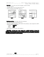
Страница 12: ...distance between the adjustment tools positioned at the entrance of the Venturi pipe of the burners For fast and semi fast burners Fig 4 loosen the check nut D rotate the ferrule G so as to adjust the distance between the ferrule and the nozzle holder P to an H value indicated in table 2 Tighten the check nut D Fig 4 Fig 5 For the triple crown burner Fig 5 loosen the V screw securing the adjustmen...

Страница 13: ...pressure mbar Type of gas Normal Max Min Table 2 G30 30 35 20 G31 37 45 25 G20 20 25 17 Main nozzles diameter 1 100 mm By pass screw nozzles diameter 1 100 mm H distance for air adjustment mm Consumption calculated with gross heat values Nominal thermal capacity kW Reduced thermal capacity kW G30 G31 30 37mbar G20 20mbar G30 G31 30 37mbar G20 20mbar G30 G31 30 37mbar G20 20mbar G30 30mbar g h G31 ...

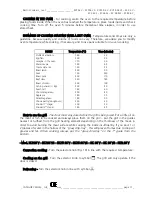
Страница 14: ... as to let the safety thermocouple B heat up Release the knob and turn it to the position desired Fig 7 Should the flame die out the safety thermocouple B will intervene automatically and close the gas cock thus blocking the gas flow to the respective burner To re ignite the burner turn the knob to the off position and repeat the ignition operations after having waited for approximately 1 minute E...

Страница 15: ...grill and plate for similar cooking way During the functioning of burners they could overheat the panrest grill by damaging the protecting enamal in irreparable way OVEN Oven control panel and use Key to symbols Manual operation PROGRAMMING KNOB Fig 9 It functions as interrupter and allows the functioning of the appliance Fig 9 Key to symbols Inside oven light Defreezing FUNCTIONS SELECTOR THERMOS...

Страница 16: ...KC 96 MS Fig 12 Sets temperature inside the cooking compartment to the value you require Fig 12 COOKING TIME PROGRAMMER Semi automatic operation Programmable time is up to 120 Turn the programmer knob to the cooking time you require as from now the program is in operation When cooking time has elapsed the appliance is switched off automatically Manual operation You can also use the appliance witho...

Страница 17: ...neral Kg Peach tart Chocolate gateau Apple pie Paradise gateau Choux pastry doughnuts Strudel 1st stage Strudel 2nd stage 160 200 170 180 190 200 100 200 220 200 200 180 200 180 180 200 200 180 20 25 50 45 22 90 220 110 180 100 20 60 40 55 50 20 20 45 How to use the grill The door must stay closed while the grill is being used Put a little oil on the meat or fish to be cooked and always place them...

Страница 18: ... on the appliance Turn the selector knob to symbol and the thermostat knob in line with off 8 Cleaning and maintenance ATTENTION Before any operation disconnect the electric supply very that the gas tap is closed and eventually that the appliance has cool down COOK TOP Wash grilles with water and liquid detergents Wash the flame traps and flame trap caps frequently with water and liquid detergents...

Страница 19: ...ng oven lamp Electrically switch off the appliance Unscrew the protective cap in glass Fig 15 Unscrew the lamp and replace it with another lamp suitable for high temperatures 300 C with the following characteristics Voltage 230 240 V Power 15 W Fitting E 14 Refit the glass cap and power up the appliance IMPORTANT At least once a year arrange for a qualified technician to inspect the appliances wit...

Страница 20: ...r terminal board T1 Safety thermostat T2 Control thermostat A A T ignition device I Push button switch MI Door microswitch P End of cooking programmer C Selector for multifunction L1 L2 Oven lamps S1 Grill indicator light S2 Thermostat indicator light V1 V2 Radial motoventilators R2 R3 Circular heating elements 1200W R1 Grill heating element 2500W 00 Black wire 11 Brown wire 22 Red wire 66 Blue wi...

Страница 21: ...ty thermostat T2 Control thermostat A A T ignition device I Push button switch MI Door microswitch P End of cooking programmer C Selector for multifunction L1 L2 Oven lamps S1 Grill indicator light S2 Thermostat indicator light B1 Contactor coil T Contactor R Relay B2 B3 Relay coil V1 V2 Radial motoventilators R1 R2 Circular heating elements 2500W R3 Grill heating element 2500W 00 Black wire 11 Br...

Страница 22: ...tion device IA Switch A T ignition device MI Door microswitch P End of cooking programmer C Selector for multifunction L1 L2 Oven lamps S Thermostat indicator light B1 Contactor coil B B2 Relay coil B3 Relay coil V1 V2 Radial motoventilators R1 R2 Circular heating elements 2500W R3 Grill heating element 2500W R4 Lower heating element 2000W R5 Upper heating element 1200W 00 Black wire 11 Brown wire...

Страница 23: ...tory this appliance was tested and set up by expert specialised personnel to ensure best operating results Any eventual assistance or regulation must be done with maximal care and attention using original spare parts For this reason it is necessary to apply to the distributor that has done the sale specifying the type of inconvenience and model of the appliance purchased The required parts for dif...

Страница 24: ...er semi fast and fast 01992297000 01992297000 Ignition plug L 800 for 3000 W burner fast 01992307000 01992307000 Ignition plug for 3600 W burner triple crown 01951047000 01951047000 01951047000 Power supply cable Supply terminal board 09950047000 09950047000 Power supply cable 4x2 5 mm2 09950817000 09950817000 09950817000 Supply terminal board 09950957300 09950957300 09950957300 Telecontactor 1195...

Страница 25: ...78700 Cock with valve for gas triple crown burner 01991608700 01991608700 01991608700 01991608700 01991608700 Safety thermocouple for 1750 W and 3000 W burners 01992288700 01992288700 Safety thermocouple for 3500 W burner 01992278700 01992278700 Safety thermocouple L 600 for 2700 W and 3100 W burners semi fast and fast 01990368700 01990368700 01990368700 Safety thermocouple L 450 for 3100 W burner...

Страница 26: ...ability to use the appliance damage caused by operation not conforming to the instructions in the use manual improvised installations adjustments and maintenance damage and or failure caused by transport in this case immediately notify the seller and or carrier The guarantee does not cover if the consumer cannot produce the compiled and documented guarantee certificate if the consumer has not sent...

Отзывы: