


IST-2138.EC01.01/C
Istruzione / User’s Manual / Manuel d’utilisation
Pag.8/18
TECNOCONTROL S.r.l. - Via Miglioli, 47 20090 SEGRATE (MI) ITALY
Tel. +39 02 26922890 - Fax +39 02 2133734
and physiological, forming metaemoglobina which is no longer able to carry oxygen to the tissues. Also, low con-
centrations (4 ppm) will anesthetize the nose.
OPERATIONAL DESCRIPTION
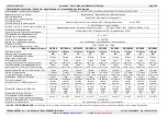
The electrochemical sensor is temperature compensated, but is sensitive to extreme humidity variations. The cali-
bration is carried out with specific gas to be detected. Anyway, it can contemporaneously detect other gases that
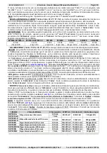
should be present in the same environment as listed in
tables 3 and 4
.
Note
that the Led are not visible when the enclosure is closed.
Preheating
: when powered, the sensor needs a time of preliminary heating of about 60 seconds. During this peri-
od the yellow LED “
FAULT
” flashes. After this period, the yellow LED light off, the green LED “
ON
” illuminates to in-
dicate normal functioning. After this period the unit is able to detect gas even if it attains the optimum stability con-
ditions after about 4 hours continual functioning.
Normal operation
: the green LED “ON” should be light on.
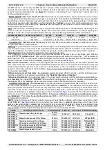
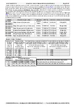
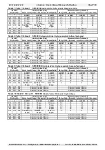
ALARMS:
different alarms levels, depending on the models, can be set by Dip-Switch (
see tables 2 and 5÷11
). There
are two different alarm methods, the normal one, will activate the corresponding relays after a fixed delay, the ad-
vanced one, operate with TLV-TWA, STEL and C value, in this case the relays will activate without delay.
The 1st red Led
(
ALARM 1
) illuminates when the gas concentration attains 1st alarm level. Under normal alarm
method, after about 12 seconds the “
ALARM 1
" relay will activate, while under advanced one, with TLV-TWA level
selected, the relay will activate without delay.
The 2nd red Led
(
ALARM 2
) illuminates when the gas concentration attains 2nd alarm level and after about 30
seconds, the “
ALARM 2
" relay will activate or without delay when TLV-STEL level is selected.
The 3rd red Led
(
ALARM 3
) illuminates when the gas concentration attains 3rd alarm level and after about 60
seconds, the “
ALARM 3
" relay will activate or without delay when TLV-C level is selected.
TLV (
T
hreshold
L
imit
V
alues
)
are defined as an exposure limit to which it is believed nearly all workers can be exposed
day after day for a working lifetime without ill effect.
TLV-TWA (
T
hreshold
L
imit
V
alue–
T
ime-
W
eighted
A
verage
)
is the time-weighted average concentration for a conventional
8-hour workday and a 40-hour workweek, to which it is believed that nearly all workers may be repeatedly exposed,
day after day, without adverse effect.
TLV-STEL
(
T
hreshold
L
imit
V
alue–
S
hort-
T
erm
E
xposure Limit
)
is the concentration to which it is believed that workers can
be exposed continuously for a short period of time without suffering from irritation, chronic or irreversible tissue
damage, or narcosis. STEL is defined as a 15-minute TWA exposure, which should not be exceeded at any time
during a workday.
TLV-C (
T
hreshold
L
imit
V
alue-
C
eiling
)
is the concentration that should not be exceeded during any part of the working exposure.
The values are recommending exposure levels that are protective to workers, OSHA (
O
ccupational
S
afety and
H
ealth
A
dministration
, of the U.S. Department of Labour) and COSHH
(
C
ontrol Of
S
ubstances
H
azardous to
H
ealth in Europe
).
Faults
:
the instrument signal different kind of failures, as listed below. The yellow Led illuminates, the "
S
" output
falls down to 0mA and the “
FAULT
”
normally activated relay deactivate. This relay, if necessary, can be used both to
signal remotely an occurred damage and to signal the absence of power to the instrument.
Yellow Led illuminates each 4 seconds (
with green Led activate
):
this happens when the “
Cartridge Sensor
” has
overcome its theoretical period of life and its correct operation is not longer guaranteed. The detector keeps on op-
erating normally but it is necessary to replace, as soon as possible, the “
Cartridge
” with a new one. The type to be
required is described on
Page 1
. The replacement procedure is described in the attached manual.
Yellow Led activate, green Led off (
FAULT relay activates and 0 mA output signal
):
this signal different kind of faults.
1)
The Dip-Switch set up is wrong, please verify (
see Tables 2 and 5÷11
).
2)
The “
Cartridge
” is not working, please re-
place with new one.
3)
If a new
“
Cartridge
” is installed or it is not correctly connected or a not compatible one is
mounted. Please check the cartridge connections and compatibility (
see on page 1
) these checks are made switching
off and on the device.
If the condition does not change, it will be necessary to replace the unit and/or send it back
to the supplier to repair.
Yellow and green Led activates (
FAULT relay activates and 0 mA output signal
):
this happens when the “
Cartridge
” is
not working. First try to perform the procedure of “
ZERO
” as described in the section
“
Test and Calibration
> Zero ad-
just
”
then disconnect and connect the unit, finally try to replace a new
“
Cartridge
”. If the condition is not change,
please replace
the unit and/or send it back to the supplier to repair.
All Led activates (
FAULT relay activates and >20 mA output signal
):
this happens when the “
Cartridge
” is not working or
gas concentration is higher than F.S. If there are not any gas leaks and the condition is not change, it will be nec-
essary to replace the unit and/or send it back to the supplier to repair.
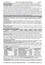
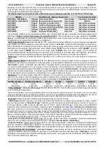
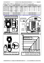
INSTALLATION
The detector must be accurately installed and testing according to the national dispositions in force on the safety of
the plants and installation of electric devices in areas with danger of explosion.
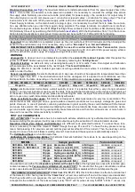
Mounting
: The
Fig. 2
shows the instrument size. The unit must be positioned vertically with the sensor downwards.
SE138EA and SE138EA-H positioning:
should be fixed at 30÷50 cm from the ceiling (
NH
3
gas is lighter than air
).
SE138EC-S and SE138EC-H positioning:
should be fixed at 1.60 m from the floor (
CO
gas is a little lighter than air).
SE138ES positioning:
should be fixed at 30÷50 cm from the floor (
SO
2
gas is heavy as air)
SE138EH positioning:
should be fixed at 30-50 cm from the floor (
H
2
S
gas is heavier than air).
SE138EHCN positioning:
should be fixed at 1.60 m from the floor for the protection of persons or over the likely
point of emission. (
HCN
gas is a little lighter than air
).
SE138EN positioning:
should be fixed at 1.60 m from the floor
(
NO
gas is heavy as air).
SE138EN2 positioning:
should be fixed at
30÷50
cm from the floor
(
NO
2
gas is heavier as air).


