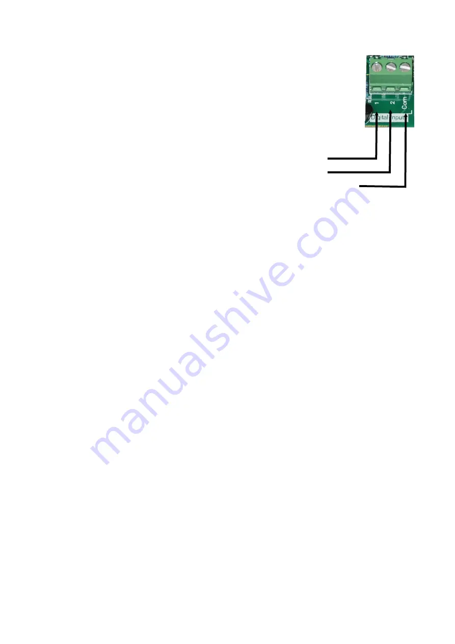
3. Wiring the Techsys back flush flow switch
Connect the Brown wire from the flow switch to Input Common on the eMiniFlush
Controller Board and connect the Black wire to Input 2.
Note: If an external DP switch is in use then the switch contacts should already be
connected between Input 1 and Input Common.
The NC flow switch contacts will open when flow increases.
Common = Brown, N.C. = Black, N.O. = Blue
4. Setup Controller
a) Power up controller.
b)
Using the up and down buttons navigate until “Access Code” is shown on the screen.
c)
Press the “*” enter button to enter the access code screen.
d) Using the up and down buttons make the valve on the screen equal to 21.
e)
Press the “*” button to lock in the access code.
f) Using the up and down buttons navigate until
“ASSIGN INPUTS” is shown on the screen.
g) Ente
r the submenu by pressing the “*” key.
h) Using the down button navigate to Input 1
i)
Check that I
nput 1 is set to “Ext-DP Flush”. If not change using procedure outlined in step k.
j)
Using the down button navigate to Input 2
k) Check that Inpu
t 2 is set to “B-F Flow SW N/C”. If not change by first pressing “*” to begin editing,
then change the value using the up/down keys. After selecting the required value use the
“*” key
to save the setting.
l)
Navigate by pressing down until the screen shows “ASSIGN OUTPUTS”.
m)
Press the “*” to enter the submenu.
n) Check that
Output 1 is set to “Fault”. If not change by using procedure outlined in step k.
o) Check that Outp
ut 2 is set to “Filter Valve 1”. If not change by using procedure outlined in step k.
p) Check that Remaining outputs are set correctly based on the number of solenoids connected. If
an output isn’t used select “Disabled”
5. Flow Switch Tuning
a. After entering the access code navigate to the timing menu
and press the “*” button to enter
the timing submenu. (see 4b)
b. Using the down button f
ind the setting “Ex B-F Flow Dly”
c. This setting controls the acceptable amount of time that flow is allowed to continue after a
backflush.
d. If the system is faulting and nothing is wrong with the backflush valve increase this setting.
This will allow a longer timer for flow to stop after a backflush.
e. The default value is 10 seconds, which should be enough for most installations.
f.
To edit press the “*” key then use the up and down buttons to adjust the value. After selecting
a new value press the
“*” key again to save the setting.
Troubleshooting
a) System is faulting and no backflush has occurred. Ether the Input settings are incorrect or the
flow switch wiring is incorrect.
b)
System doesn’t flush when the external dp switch is triggered. Ether faulty DP Switch,
incorrect Input settings, or incorrect DP switch wiring.
c)
System won’t fault when the backflush flush flow switch is held open. Incorrect input settings
or incorrect flow switch wiring.
Input 1
Input Common
Input 2


