TSR 2800-20-DC Router’s Hardware Installation Manual
- 2 -
indicator
forwarding the data.
6 LINK
Standard Ethernert0
LINK indicator
If Ethernet0 is linked, the indicator
is on.
7 FE1
10/100M
port1
The port is connected by the
twisted pair.
8 FE0
10/100M
port0
The port is connected by the
twisted pair.
9
CON
Console port
A port used for system control
10
AUX
AUX port
Auxiliary serial port
11 USB
USB
port
12 SWITCH Power
switch
"ON" means the switch is opened,
while “OFF” means the switch is
closed.
13
Power
AC power socket
AC100-240V
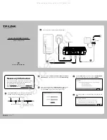
The back template of TSR 2800-20-DC router is shown in the following figure:
Table 1-3 Parts at the front template of TSR 2800-20-DC router
No. Abbrev.
Name
Remarks
1
GND
Grounding column
The grounding must be fine.
2
SLOT4
Slot 4 for expanded interface card
The 8-path asynchronous card is
supported.
3
SLOT2
Slot 2 for interface card
The single-serial-interface card,
the dual-serial-interface card and
the 8-path asynchronous card
are supported.
4
SLOT1
Slot 1 for interface card
The single-serial-interface card,
the dual-serial-interface card, the
8-path asynchronous card and
the single-path E1 card are
supported.
5
SLOT3
Slot 3 for expanded interface card
The 8-path asynchronous card is
supported.
1.2 Characteristic Parameters of the Router
The attribute parameters of TSR 2800-20-DC are shown as follows: