Technosoft 2020
19
iPOS80x0 BX-CAN/-CAT Technical Reference
3.4.4
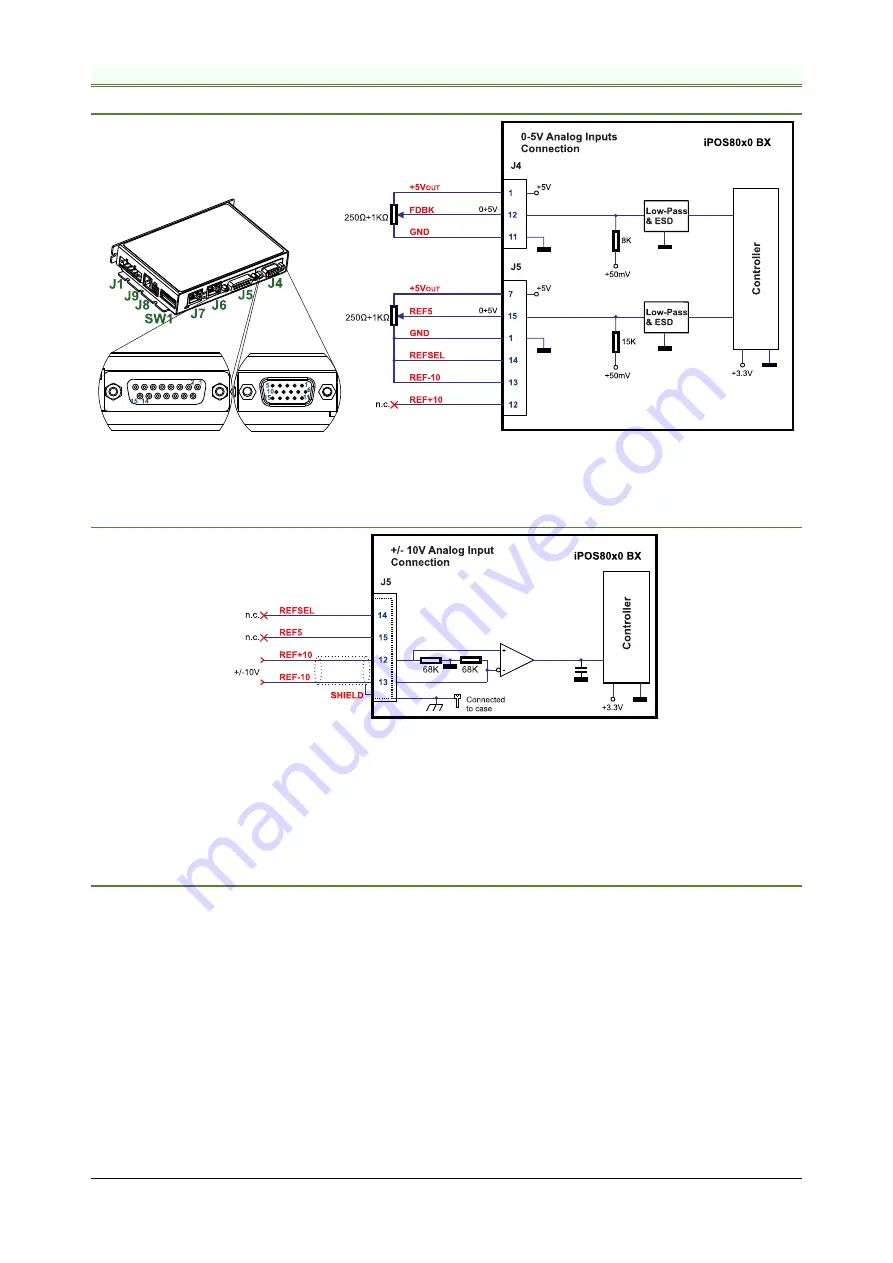
Analog Inputs Connection
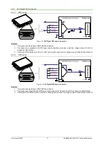
3.4.4.1
0-5V Input Range
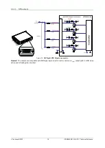
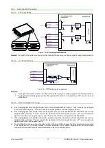
Figure 3.7.
0-5V
Analog inputs connection
Remark:
The length of the cables must be up to 30m, reducing the exposure to voltage surges in industrial environment.
3.4.4.2
+/- 10V Input Range
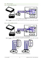
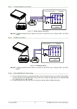
Figure 3.8.
+/-10V Analog inputs connection
Remarks:
1. The length of the cables must be up to 30m, reducing the exposure to voltage surges in industrial environment.
2. To Switch Ref and Fdbk signals, set the TML register ASR bit 10 to 1. It allows the +/-10V circuit to be used
as feedback.
3.4.4.3
Recommendation for wiring
a) If the analog signal source is single-ended, use a 2-wire shielded cable as follows: 1
st
wire connects the live signal
to the drive positive input (+); 2
nd
wire connects the signal ground to the drive negative input(-).
b) If the analog signal source is differential and the signal source ground is isolated from the drive GND, use a 3-wire
shielded cable as follows: 1
st
wire connects the signal plus to the drive positive input (+); 2
nd
wire connects the
signal minus to the drive negative input (-) and 3
rd
wire connects the source ground to the drive GND
c) If the analog signal source is differential and the signal source ground is common with the drive GND, use a 2-wire
shielded cable as follows: 1
st
wire connects the signal plus to the drive positive input (+); 2
nd
wire connects the
signal minus to the drive negative input (-)
d) For all of the above cases, connect the cable shield to the drive GND and leave the other shield end unconnected
to the signal source. To further increase the noise protection, use a double shielded cable with inner shield
connected to drive GND and outer shield connected to the motor chassis (earth).


