BIKE XT: Service & Maintenance manual - rev. 2.0
Page 2.3
•
Power supply
name
type of connector
connection
CN1
PANDUIT 6-pin
to mains electricity supply
CN2
PANDUIT 8-pin
to alternator interface board
•
Alternator interface board
name
type of connector
connection
CN1
AMP MATE-N-LOCK 15-pin F.
to CPU circuit board
CN2
AMP MATE-N-LOCK 6-pin F.
to alternator
CN3
AMP MODU I 4-pin M.
to power supply
2.5.2.
W
IRING
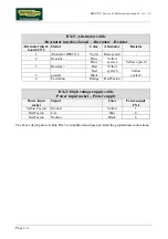
BX-1: Internal connecting cable
CPU – Alternator interface board
CPU/CN1
Signal
Color
Alternator interf.
board/ CN1
1
+12 V
Red
1
2
+ 5 V
Orange
2
3
ground
Black
3
4
-12 V
Blue
13
5
Alternator RPM X 6
Violet
5
6
Alternator control frequency
Brown
6
On some machines, the signal desi12 V in the above table is actually 10.5 V.
BK-7: Heart rate display cable
CPU – Cardio receiver
CPU/CN4
Signal
Color
Receiver
1
+5 V
Red
1
2
Pulse per beat
Blue
2
3
ground
Black
3
BK-6: Low voltage supply cable
Power supply – Alternator interface board
Power supply/
CN2
Signal
Color
Alternator interf.
board/ CN3
2
+ 5 V
Yellow
4
5
+ 12 V
Red
2
6-7-4
ground
Black
3
8
- 12 V
Blue
1
Содержание BIKE XT
Страница 1: ...SERVICE MAINTENANCE MANUAL REV 2 0...
Страница 2: ......
Страница 4: ......
Страница 16: ...BIKE XT Service Maintenance manual rev 2 0 Page 4 2 Page intentionally left blank...
Страница 30: ...BIKE XT Service Maintenance manual rev 2 0 Page 6 12 Page intentionally left blank...
Страница 46: ...BIKE XT Service Maintenance manual rev 2 0 Page 7 16 Page intentionally left blank...
Страница 54: ...BIKE XT Service Maintenance manual rev 2 0 Page 8 8 Page intentionally left blank...
Страница 58: ...BIKE XT Service Maintenance manual rev 2 0 Page 9 4 Page intentionally left blank...
Страница 66: ...BIKE XT Service Maintenance manual rev 2 0 Page 11 6 Page intentionally left blank...
Страница 67: ......


