13
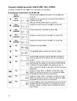
The three outputs
A1
,
A2
and
A3
for the stop valves are switched on if the associated flow
thresholds
min1
(540 l/h),
min2
(960 l/h) and
min3
(1440 l/h) are exceeded.
The low switch-on thresholds makes it probable that the last workstation is rinsed at least
several times a day and that no standing water collects.
Control of cascade switching with UVR1611
The outputs for stop valves
A1
–
A3
are switched on via comparison functions. The associat-
ed switch-on and switch-off thresholds are identical to those of the UVR61-3.
Cascade switching with circulation line
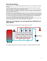
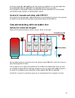
Hydraulics schematic diagram
Figure with fresh water stations version, version “Pump on the right“
The circulation pump is connected only to the always ready FRISTAR 1 and must not gener-
ate a flow larger than 18 l/min.
If the system is to be switched via UVR61-3R or UVR63, three FRISTAR modules at most
are possible. Program 480 for switching modules 2 and 3 via outputs
A1
and
A2
must then
be used. The circulation pump is switched via the distance
S5
–
S4
on output
A3
.
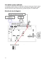
If UVR1611 is used, the circulation pump can be controlled with the “circulation” function.
Circulation pump


