Issue/Rev. 0.3 (8/02)
MN02004 • 5
Section 2 – Service (continued)
If thrust washer shows signs of wear but is not
cracked, turn washer over.
• In some of the older turbine meter designs, it will
be necessary to apply a small amount of heat to
the stator around the thrust washer area to re
move the washer.
• On models after serial number 229T, the thrust
washer is secured in place with a small amount
of Locktite No. 72-41. This can also be removed
by applying a small amount of heat around the
washer. The washer can then be turned over
for reuse. If the new bearing surface shows
evidence of Locktite (yellowish color), it can
be removed with acetone.
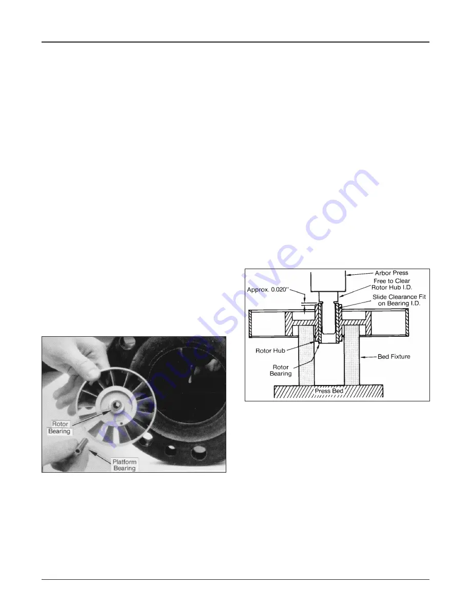
10. Remove rotor and platform bearings, Figure 11,
using extreme care that the platform bearing is
not permitted to fall from the rotor since, due to
the brittleness of the bearing, a fall could result in
severe damage. Inspect outside surface of bearing
for grooves, chipping, roughness, and cracks, as
well as cracks in end surfaces.
When removing the rotor from a bidirectional
turbine meter, it is necessary to remove the
downstream deflector ring. Remove the set
screw and slide the ring out. When reinserted,
the ring must be relocated exactly in its former
position as the ring properly positions the
downstream stator in relation to the upstream
stator.
Figure 11
Inspect inside surface and end surfaces of rotor
bearing for same defects as for platform bearing.
If bearing surfaces show no defects, the bearing
will be suitable for reuse in most cases.
•
Bearing wear is minimal and bearing
replacement is usually required only due
to damaged surfaces.
11. Should rotor bearing require replacing, it is
suggested that rotor assembly be returned to
Measurement Solutions for rework. See “Return
Procedures,” Page 2.
Rotor bearing replacement can be done in the field
by the following repair procedure.
a. With proper tool and fixture, Figure 12, the
old rotor bearing may be forced out of the
rotor hub with an arbor press. Care must be
taken in the selection of tool and fixture to
insure a “straight line” or axial press only.
Push the bearing out with a smooth, steady
motion.
b. The new bearing may be installed with the
same equipment used to remove the old
bearing. Center the bearing carefully in line
with the hub bore before pressing. The
bearing material has been selected for its
hardness and wear characteristics, but may
be chipped or broken if mistreated. Press the
bearing into the rotor hub to achieve equal
protrusion within 0.005" from both hub faces.
Figure 12
12. Remove upstream stator with shaft and inspect
as described in Step 9. On most unidirectional
models, holes are in nut end of stator (Figure 13).
In some bidirectional turbine meters, two
downstream stators are used. Therefore, the
holes will be located as shown in Figure 10.
13. For a unidirectional turbine meter, it is not
necessary to remove deflector ring in order to
service meter internals. If ring is removed, it must
be relocated exactly in its former position when
reinserted as ring properly positions upstream
stator in relation to down-stream stator. If
necessary to remove, remove set screw and
slide ring out from upstream end of meter,
Figure 14.


