4 • MN02004
Issue/Rev. 0.3 (8/02)
Section 2 – Service (continued)
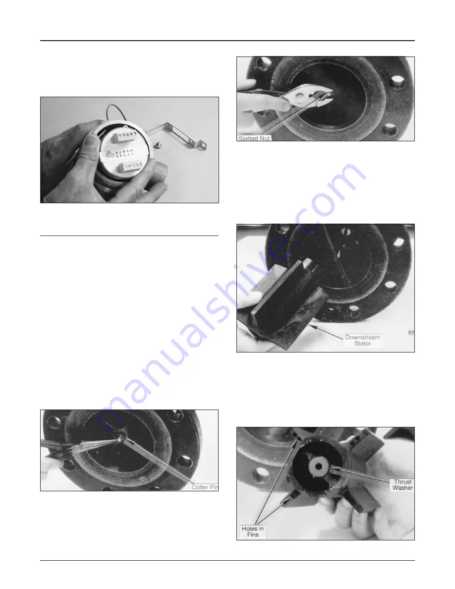
3. Disconnect output wiring and remove preamp from
junction box, Figure 6.
4. For reassembly, reverse procedures.
Figure 6
Removal and Servicing of Meter lnternals
1. Drain product from line. Drain in direction of flow
(if possible).
2. Make certain power has been disconnected to
meter.
3. Remove junction box cover, disconnect output
wiring and conduit where required.
4. Make certain meter is properly supported before
re-moving bolts and nuts.
5. With meter removed, check straightening
section to make certain tube bundle is clean
and free from damage.
6. If necessary to remove pick-up coil and
preamplifier, refer to procedures outlined above.
7. Remove cotter pin and slotted nut from
downstream end of meter, Figures 7 and 8.
Figure 7
Figure 8
8. Remove downstream stator, Figure 9. In a
unidirectional turbine meter, the stator is located
by a Woodruff key. Care should be taken that the
Woodruff key is not lost. In a bidirectional turbine
meter, there is no Woodruff key; the two stators
are located by two deflector rings.
Figure 9
9. Inspect the holes in the downstream stator fins
on the thrust bearing end, Figure 10, to make
certain they are open and the inside of the
stator is clean. Inspect thrust washer for signs
of roughness, grooves, or cracks.
Figure 10


