technetix DBD-1200 Скачать руководство пользователя страница 14

12

Technetix Group Limited

Rev.1.0.1_0217

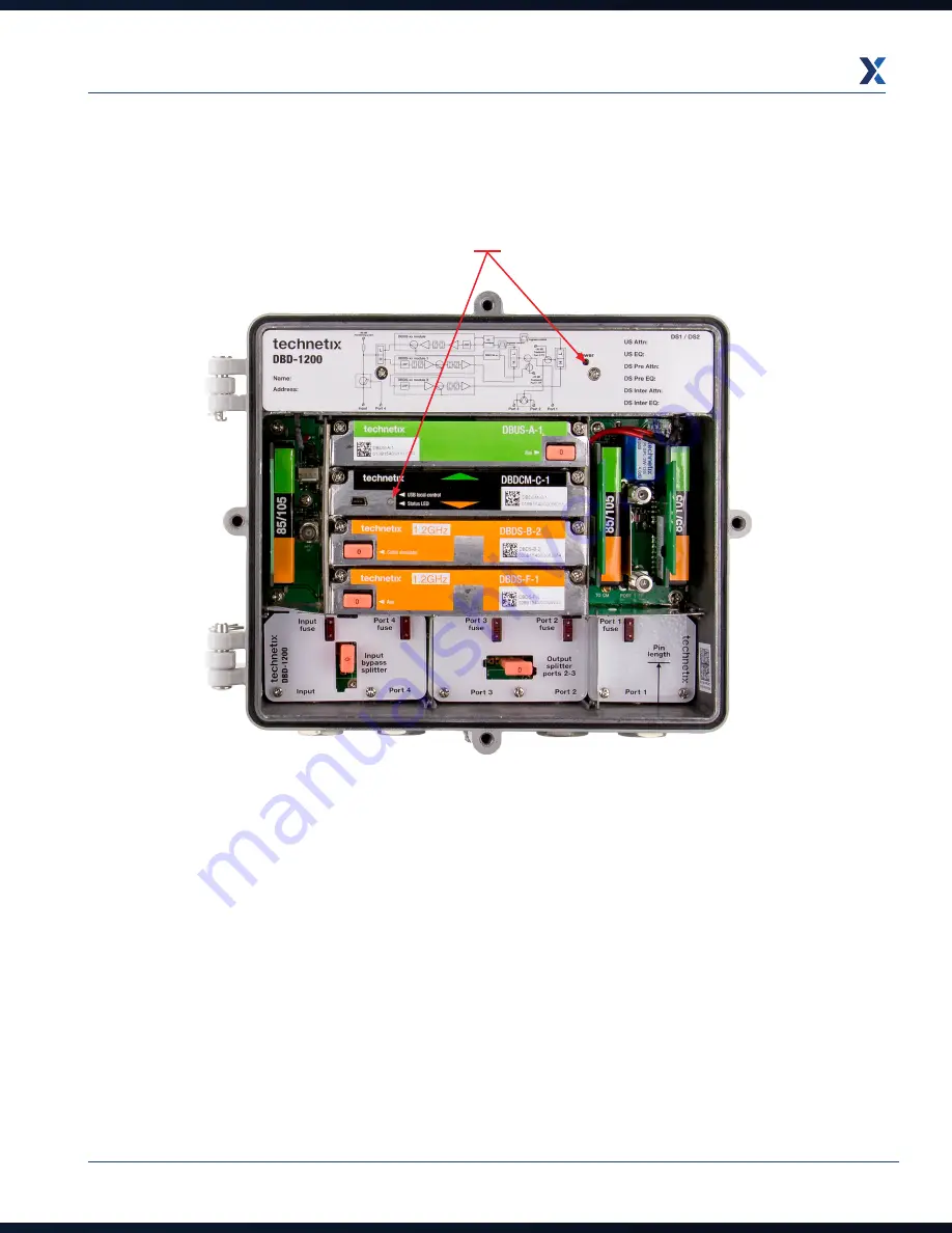
3.  Install the fuse (power director) ensuring it is fully inserted into the fuse holder in the relevant port for incoming AC  
  power. Check that the amplifier DBDCM module LED (DBDCM-Ax = red, DBDCM-Cx = green) and the PSU LED.

(Figure 5)

Содержание DBD-1200

Страница 1: ...DBD 1200 USER GUIDE Online Email customer service vdl technetix com Website technetix com Rev 1_0 1_0217 ...

Страница 2: ...direct to cabinet back panel 7 3 2 Installing coaxial 8 3 3 Closing amplifier 9 3 4 Configuring the PSU 10 3 5 Powering up the amplifier 11 3 6 Downstream configuration 13 3 7 Downstream activation 14 3 8 Upstream activation 20 Chapter 4 Maintenance 24 4 1 PSU replacement 24 4 2 Amplifier module replacement 27 Chapter 5 Optical node 1x1 29 5 1 General installation 29 5 2 Downstream connection 29 5...

Страница 3: ...king knowledge of coaxial cable systems and cabling practices Specific tools list The following tools and supplies are required when installing a DBD 1200 6mm hex key for the lid bolts Set of crosshead screwdrivers Pair of linesman s pliers only needed if changing the diplex filters Torque wrench Appropriate bolts screws washers for mounting the DBD 1200 see page 7 Appropriate USB for the DBDCM A ...

Страница 4: ...ttings Applications b Select Unknown sources 2 Copy the BLA vx x apk file to the device a Go to Applications Settings Wireless and Network USB Settings b Select Mass storage c Connect the phone tablet to your PC d The drives of the phone will appear in file explorer e Copy the apk file to a suitable place on the phone tablet 3 Go to applications my files 4 Browse to the apk file 5 Click the BLA ap...

Страница 5: ...amplifier 44dB 53dbmV output DBDS B 7 ET Main 1 2GHz DS amplifier 44dB 53dbmV output ET 25dB tilt DBDS F 1 Bridger 1 2GHz DS amplifier 44dB DBDS F 2 Bridger 1 2GHz DS amplifier 44dB DBDS F 5 1 Bridger 1 2GHz DS amplifier 44dB 53dbmV output Control module DBDCM A 1 AGC ALSC FSK USB A Mini USB DBDCM B 2 AGC ALSC DOCSIS transponder compatible USB A DBDDM A 1 DOCSIS 3 0 transponder RS232 MCX DBDDM B 1...

Страница 6: ... simulation is provided by a JXP module The DBD 1200 has a highly efficient long life switch mode power supply to provide the power Gas tubes at the input and output ports protect the RF circuits in the event of lightning or mains power surges Benefits Full digital control and setup with integrated ALSC Improved intermodulation distortion performance innovative GaN technology operates to 1218 MHz ...

Страница 7: ...12 11 Port power directors fuses micro2 automotive 12 Input 20 dB test point omnidirectional 13 Output downstream 20 dB test point upstream injection 20 dB test point 14 Output splitter location 2 way splitter PI SPL 2W 12G directional coupler tap 8dB TX DC 8 tap 12dB TX DC 12 15 Input RF port PG11 thread with optional 5 8 reducing ring for 5 8 threaded connectors 16 Port 4 RF bypass output port P...

Страница 8: ...that are attached onto the side of the unit using the 2 x 6mm threaded 10mm long countersunk screws provided see the pictures below Once the brackets are attached the amplifier can be offered up to the mounting location to mark the bracket cut outs onto the mounting surface ready for holes to be made for the mounting bolts screws The amplifier can then be attached to the mounting surface using app...

Страница 9: ... a cabinet back panel use the rear 6mm bolt holes with 2 x 6mm threaded bolts figure 1 Do not use fixings that are longer than 6mm otherwise they may protrude through the back board The bolt total length dimension to be used is 6mm back board thickness dimension washer thickness dimension Housing 6mm threaded bolt holes 140mm centres Figure 1 ...

Страница 10: ...or pin length 30 5mm PG11 connector pin length from connector housing shoulder to pin tip 28mm Figure 2 Use the internal pin length guide to check the correct pin length Place the PG11 connector housing shoulder against the amplifier housing lip to check the pin length 2 Tighten the connectors into the housing in accordance with the connector manufacturer s specification The maximum torque force f...

Страница 11: ...gain in sequence and tighten to the final torque setting Following this sequence will ensure 1 The rubber gasket between the lid and the amplifier housing is sealed correctly providing a sound watertight seal to prevent water ingress 2 A good RF seal between the RF gasket in the lid and the amplifier housing to prevent RF ingress egress 3 A good lid to housing contact for the dissipation of amplif...

Страница 12: ...ss port using a power inserter 2 Remote powering Maximum AC power passing 10 See page 27 for removal installation of PSU unit Powering routing Input port Output port 2 Output port 1 Input bypass port Local powering VAC Remote powering Output port 3 Fusing power directors Referring to the network design documentation remove any fuses not required for passing power ...

Страница 13: ...in the amplifier specification and the network design drawing calculation 3 5 Powering up the amplifier 1 When the device is configured and once the amplifier is mounted into the network location temporarily remove the fuses Connect the RF cables to the relevant RF ports and connect the earthing grounding wire in accordance with local electrical installation regulations on the right hand side of t...

Страница 14: ...1 0 1_0217 3 Install the fuse power director ensuring it is fully inserted into the fuse holder in the relevant port for incoming AC power Check that the amplifier DBDCM module LED DBDCM Ax red DBDCM Cx green and the PSU LED Figure 5 ...

Страница 15: ...ath as required by the network design documentation With the selector installed as shown pin 5 is to the top so the through leg is to RF Port 3 and pin 5 is passing RF into the amplifier Pin 5 is the tap leg Output splitter selector Referring to the network design documentation configure the output splitter by installing a 0 pad jumper into the right hand three holes of the five holes to pass all ...

Страница 16: ...Connect a spectrum analyser to the input 20 dB test point then measure and record the RF pilot frequencies input levels as per the design drawings Note ensure all amplifier ports are connected to a 75Ω terminated load so that the RF test instrument readings are correct ...

Страница 17: ...Rev 1 0 1_0217 Electronic setup downstream Note For advanced settings and configurations please refer to the latest release of our BLL Using a laptop with the Technetix BLL software installed connect the laptop and the amplifier ...

Страница 18: ...it is deployed 1 With the BLL software running click on Scan Bus at the bottom left of the application screen This enables the BLL application to connect to the DBDCM module Once the amplifier communication is established the amplifier type name will appear at the top left of the application With the latest versions BLL the above is done automatically ...

Страница 19: ... Send to amp to set these values electronically 3 The downstream Inter stage equaliser and Inter stage attenuator can be set as required by the network system design documentation in two ways You can set them in the amplifier schematic inter stage tabs or in the table to the right of the application screen see the screen shot below Once the values are set in the application click on Send to amp to...

Страница 20: ... system design documentation Remember once a value is set in the Pre stage equaliser field the amplifier schematic or the parameter view table to the right of the application screen click on Send to amp to set these values electronically Then check the tilt slope between the pilot frequencies on the spectrum Pre stage Equaliser dB Pre stage Attenuator dB 5 Next set the pilot frequencies levels to ...

Страница 21: ...using a fine tip permanent marker pen They can also be saved electronically To save the amplifier settings electronically enter the amplifier ID number into the Amplifier name field as shown on the right Next click on the File tab and then click on Save backup file File name will be amplifier name as in the screen shot above and the date at time of saving ...

Страница 22: ...or return path sweep system to the network return path upstream alignment level and add 20 dB for the 20 dB test point so that the correct level is injected into the amplifier Use a signal generator with 2 x CW carriers at 16 and 64 MHz at a 40 dBmV output level 3 Using a laptop with the Technetix BLL software installed connect the appropriate USB lead between the laptop and the amplifier DBDCM mo...

Страница 23: ... with the technician at the next amplifier node on the upstream This technician s RF spectrum analyser test meter should be connected to the test point where the return path signals can be seen from a signal generator Advise the technician at the amplifier being setup to adjust the upstream tilt so that the 2 x CW signals are at the same level Equaliser dB ...

Страница 24: ... the return path sweep generator output to the required return path upstream alignment level plus 20 dBmV to overcome the 20 dB test point Connect the test equipment return sweep output to the 20 dB output test point and the return sweep RF forward data to the 20 dB input monitoring test point Using the BLL software adjust the amplifier upstream tilt then the attenuation to obtain a flat sweep res...

Страница 25: ...y enter the amplifier ID number into the Amplifier name field as shown below Use the same name as for the upstream activation 4 Next click on the Tools tab and then click on Save current state to file File name will be the amplifier name as in the screen shot and the date at time of saving ...

Страница 26: ...Ensure line power is disconnected before starting PSU replacement 1 Remove the 2 x PSU cover plate crosshead screws then the PSU cover plate 2 Unscrew the 2 x PSU holding screws Remove the PSU by lifting it carefully and sliding the grounding pass through PSU leads clips out of their slots ...

Страница 27: ...25 Technetix Group Limited Rev 1 0 1_0217 3 Next using a screwdriver release the PSU electrical connectors securing clips and unplug the leads 4 Remove the PSU from the DBD 1200 housing ...

Страница 28: ...he housing and secure the PSU into place with the 2 holding screws c Slide the grounding pass through PSU leads clips into the housing slots ensuring they are seated down to the bottom of the slots a Replace the PSU cover and secure it with 2 x crosshead screws b Apply power and ensure that the PSU green LED is on indicating that the PSU is functioning ...

Страница 29: ... it in place Grip the ends of the module and apply a rocking motion whilst pulling the module at the same time until it comes out of the housing 2 To install the module place it into the downstream slot and push firmly and squarely down onto the unit until it is fully seated Secure it by tightening the 2 x screws to a torque value of 1 5 Nm Upstream 1 To remove a module unscrew the 2 x screws hold...

Страница 30: ...unit until it is fully seated Secure it by tightening the 2 x screws to a torque value of 1 5 Nm 1 To remove a diplex filter Grip the centre of the PCB with a pair of linesman s pliers and take care to gently pull out the diplex filter vertically avoiding risk of damage to the connectors 2 To install a diplex filter Guide the filter guide pegs onto the slots in the amplifier circuit board and then...

Страница 31: ...external fibre through the fibre tray using the outer guide lines as much as possible as these have a wider bending radius for thicker pig tails 5 2 Downstream connection The DBRX A 1 can receive wavelengths from 1100 until 1610nm from the headend Connect the downstream fibre to an optical power meter and check that the level falls within the operating window of the optical AGC from 7dBm to 1dBm O...

Страница 32: ... slots are visible A test point is located on all laser boards this will align your Optical Modulation Index OMI to a satisfactory level Depending on the number of upstream channels you can theoretically divide the 100 OMI available over the respective channels The higher the OMI percentage the better your uplink The upstream RF level can be measured by using an MCX to F female adapter DBLB TP CON...

Страница 33: ...y level to achieve the ideal OMI This can be done by using the block diagram or by using the menu on the right The IDS switches are available to use when ingress occurs and you need to troubleshoot into the right segment The downstream module section shows the optical received power The attenuators can control the RF gain from the node The equalizers must be set according to the cable type and len...

Страница 34: ...an be reused in other amplifiers If an input splitter tap is installed this can be removed at this time as well Note all procedures can be executed while the amplifier is powered up Install the fibre tray in the position of the input diplex filter and secure it with a screw Insert the optical receiver module in the bottom slot replacing the RF forward amplifier and the upstream transmitter into th...

Страница 35: ...he DBx software All settings for the optical module can be executed the same configuration as a RF amplifier The incoming fibre needs to be inserted into the amplifier through the lid port 5 8th thread Ensure the cable is securely fitted inside clips Close DBx product ensuring all bolts are secured correctly 05 04 06 ...

Страница 36: ...DBD for the 2nd slot in DBTX A 1 DBLB TP CON MCX to F Female adapter for measuring upstream RF level Other output power options are available please contact your local sales representative for further information Copyright 2017 Technetix Group Limited All rights reserved This document is for information only Features and specifications are subject to change without notice Technetix the Technetix l...

Страница 37: ...Technetix Group Limited Rev 1_0 1_0217 ...

Отзывы: