


23
TL-CAV-01-HDV User Manual
www.tlnetworx.com
5.2
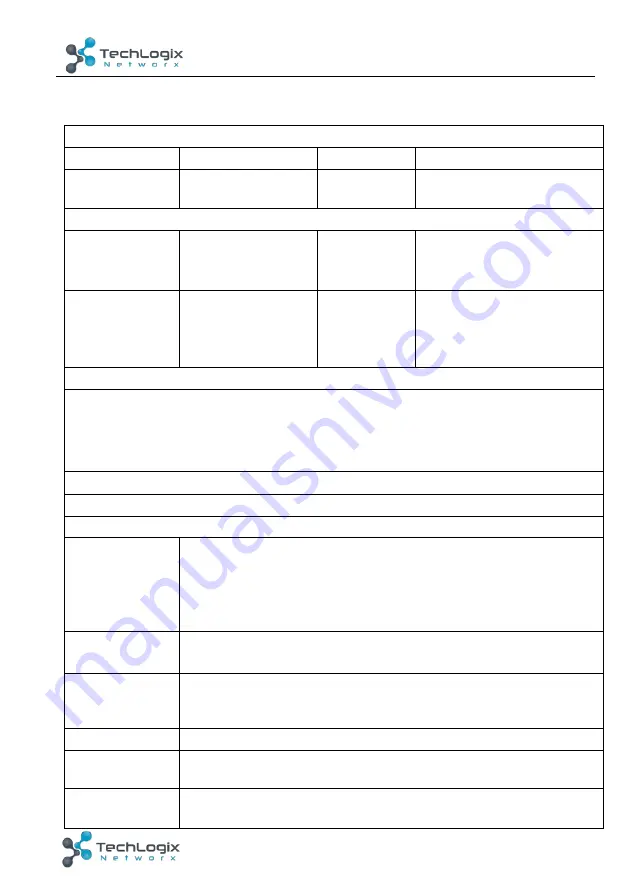
Receiver
Video Ports
Input
1 x HDBT+Power
Output
1 x HDMI
Input Connector RJ45
Output
Connector
19-pin Type A HDMI female
Audio Ports
Input
1 x MIC
Output
1
x
amplifier
(
2x20Watt@4
Ω
)
,
1 x analog audio
(
LINE OUT
)
Input Connector 3-pin
pluggable
terminal block
Output
Connector
4-pin pluggable terminal
block;
3-pin pluggable terminal
block
Control Ports
1 x USB-A
1 x IR OUT (3.5mm jack)
1 x RS232 (3-pin pluggable terminal block)
1 x TCP/IP (RJ45)
Other Ports
1 x REMOTE MUTE(2-pin pluggable terminal block)
General
Resolution
1920x1080 (24/25/30/50/60Hz)
,
1920x1080 (50/60Hz)
,
1920x1080i (50/60Hz), 1600x900, 1366x768, 1280x720,
1920x1200, 1680x1050, 1440x900, 1360x768, 1280x800,
1600x1200, 1400x1050, 1280x1204, 1024x768, 800x600,
640x480
Deep Color
24-Bit at 1920x1080 (24/25/30/50/60Hz) 4:4:4;
48-Bit at 1920x1080 (50/60Hz) 4:4:4
Audio Format
HDMI embedded audio: PCM/Dolby/DTS
MIC input audio: PCM/Dolby Digital/DTS/DTS-HD
Analog output Audio: PCM
Signal Extension Up to 30 meters @ 1080p/60 via Cat5e/6a cable.
Bandwidth
10.2Gbps
HDMI Standard
Support HDMI1.4 and HDCP1.4


