RADIO INSTALLATION
(Continued)
4 5
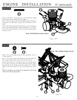
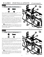
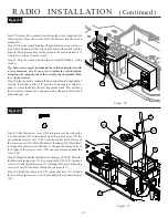
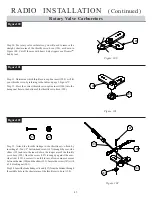
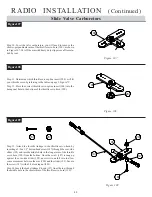
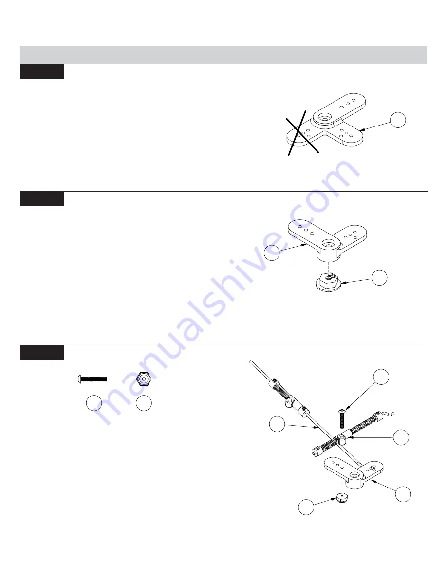
Step 33. Attach the throttle linkage to the throttle servo horn by
inserting a 2-56 x 1/2" button-head screw (187) through the over-ride
slider (195) and into the inner hole in the longer arm of the throttle
servo horn (190). Once the screw (187) is snug up against the over-
ride slider (195), unscrew it one full turn to allow some movement
between the arm (190) and the slider (195). Secure the screw (187) with
a 2-56 locking nut (201).
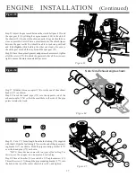
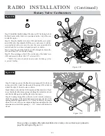
Step 34. Insert the brake linkage Z-bend (197) from the bottom, through
the middle hole in the shorter arm of the throttle servo horn (190).
Figure 102
Figure 100
Figure 102
Figure 101
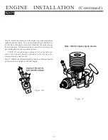
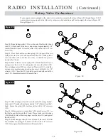
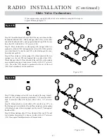
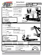
Step 31. Determine which throttle servo spline insert (200) will fit
your throttle servo by referring to the table on page 3, Figure 7C.
Step 32. Press the correct throttle servo spline insert (200) into the
hexagonal hole in the bottom of the throttle servo horn (190).
Figure 100
190
Step 30. For rotary valve carburetors, you will need to remove the
straight, shorter arm of the throttle servo horn (190), as shown in
Figure 100. Cut off the arm with heavy duty clippers or a Dremel
TM
hobby tool.
Rotary Valve Carburetors
Figure 101
200
190
197
201
187
195
190
187
201


