124
54
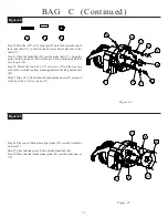
BAG D (Continued)
2 5
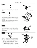
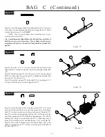
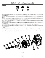
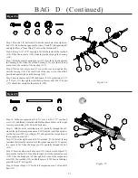
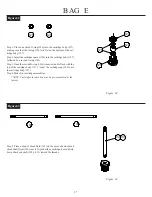
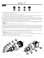
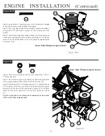
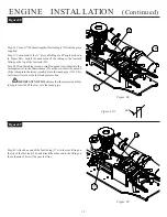
Step 19. Place the rear shock tower (123) over the rear of the gearbox
assembly (82)(83) so that the top holes line up. Place a gold ball stud
washer (9) over each of the 4-40 x 1/2" cap-head screws (31). Secure
the rear shock tower (123) to the gearbox (82)(83) by threading the 4-
40 x 1/2" screws (31), with washers (9) attached, throught the tower
(123) and into the gearbox (82)(83).
Figure 58
Figure 59
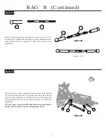
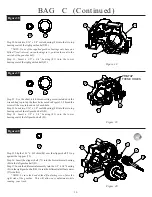
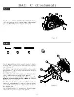
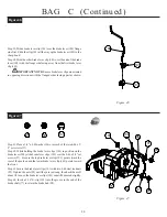
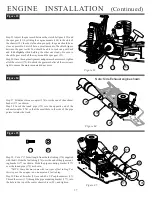
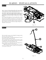
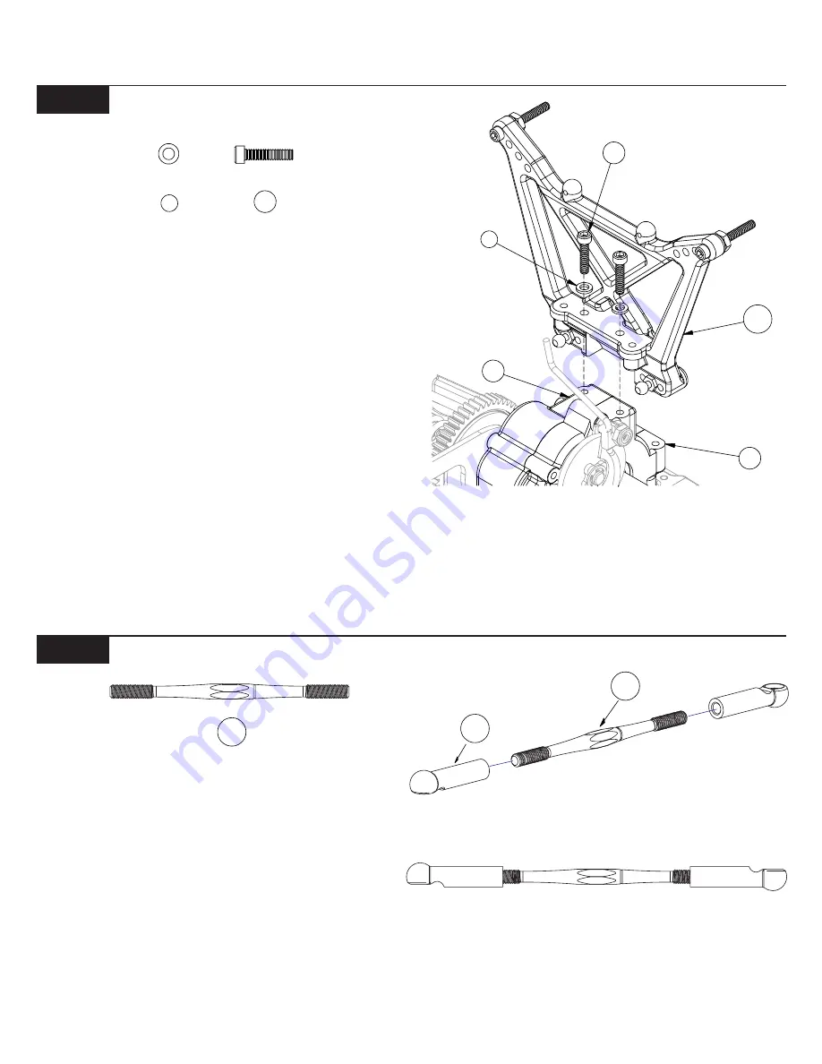
Step 20. Thread a long plastic rod end (54) onto each end of a 2-1/2"
turnbuckle (124). Tighten both rod ends (54) equally until the rod is
the same length as the one shown in Figure 59A. Make two of these
rear camber link assemblies.
*NOTE: The turnbuckles have right and left hand threads at
opposite ends. This allows the length of the rods to be adjusted
without removing them. Install all turnbuckles with the machined
groove to the left side so all adjustments will be made in the same
direction.
Figure 59
9
31
Figure 59A
Figure 58
31
9
123
83
82
124


