background image

11

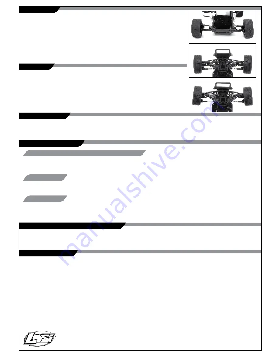
Toe-In

Ride Height

Radio/Speed Control and Motor

Service/Repair

Camber

Chassis

Cleaning

Rebuilding the Differential

Disassembly

If you have any problems other than those covered in the troubleshooting section, please call the electronics service 
department at (877) 504-0233. 

They will be able to give your specific problem additional attention and instruct you as 

to what needs to be done.

If you have any questions other than those covered in the troubleshooting or maintenance sections, please call 
(877) 504-0233.

Performance can be hindered if dirt gets in any of the moving suspension parts. Use compressed air, a soft 
paintbrush, or toothbrush to remove dust or dirt. Avoid using solvents or chemicals as they can actually wash 
dirt into the bearings or moving parts as well as cause damage to the electronics. 


The gears in the differential will wear over time. The same is true for the outdrives, 
driveshafts, and rear axles. We suggest using a small rag or paper towel to lay out the parts 
you remove to make it easier to reassemble.

1. Unplug the motor.
2. Remove the two screws attaching the roll cage at the back as well as the two at the top and bottom of the shock tower. 
3. Remove the two screws attaching the rear brace to the transmission and the four screws at the bottom of the 
    chassis holding the gearbox in place and slide it out of the chassis. 
4. Remove the steel outdrives from either side then the left side of the gearbox  by removing the four screws. 
5. Carefully remove the large plastic sun gear and the bevel gears on either side of it. You can use the removed 
    differential assembly as a guide for putting together the replacement unit (a little Team Losi T

eflon grease 

    #LOSA3066 or LOSA99208 can be applied for even better performance). 

6. Remove the center mounted idler gear from the gearbox. Remove the shaft and push out the ball bearings 
    from either side. Install these bearings in the new gear. 

More Camber

More Camber

Normal

More Toe-In

This is the height the chassis sits and runs at. Spring spacers included with the Mini Sprint, when installed between 
the shock top and spring, will increase the pre-load on the spring and raise the chassis. You may want to try this when 
running on extremely rough surfaces.

Camber is the angle of the tires to the racing surface when viewed from the front 
or rear of the truck. You want to keep both the front and rear tires straight up and 
down or leaning in at the top very slightly. If you are running on carpet or similar 

high traction surfaces, you may find leaning the tires in a bit more helps. This 

adjustment is made with the threaded links extending from the front or rear  
bulkhead to the spindle carrier or rear hub. Making the camber rods shorter 
increases the camber and lean-in of the tire, while making the camber rods longer 
decreases the camber.

This is the relationship of the left and right side tire to one another. Ideally you 
want the front of the tires to be pointed inward toward each other just slightly 
when viewed from above. This makes the model track straight and stable. This is 
controlled with the threaded steering rods on either side. As you make them 
longer you will increase the toe-in and vice versa.

Содержание Mini Sprint

Страница 1: ...l supervision for drivers under 14 It is critical that you read all of the instructions in order to operate your model correctly and avoid unnecessary damage Please take a moment to look over all the...

Страница 2: ...t in product malfunction electrical issues excessive heat FIRE and ultimately injury and property damage Read all safety precautions and literature prior to use of this product Never leave the battery...

Страница 3: ...all four 4 AA batteries into the battery holder Pay close attention to the correct direction of the positive and negative ends as marked in the tray Once all 4 batteries have been installed reinstall...

Страница 4: ...Now you are ready to turn on the transmitter You should notice on the back of the transmitter a similar blinking Orange LED under the translucent cover 5 Both the receiver and transmitter blinking Ora...

Страница 5: ...e servo gears Motor doesn t run Motor plugs loose Plug in completely Motor wire broken Repair or replace as needed ESC damaged Call Electronics Tech ESC gets hot Motor over geared Put smaller pinion o...

Страница 6: ...e following is an overview of the various functions and adjustments found on the Mini Sprint radio system Since the Mini Sprint operates on a radio signal you control it is important for you to read a...

Страница 7: ...load protection When the motor is stalled the ESC will automatically shut off the power output with the red LED flashing for 30seconds After 30 seconds the ESC will return to normal operation Note The...

Страница 8: ...e ESC will return to the Battery Selection mode as mentioned above ESC Mode Selection During normal operation GREEN LED indicates the ESC is in the motor off position Forward Reverse Mode GREEN LED is...

Страница 9: ...nd themselves together Please turn off both the vehicle and transmitter to remove the Bind plug from the receiver Failing to remove the Bind plug will cause the transmitter to attempt to rebind every...

Страница 10: ...rotating the knob counterclockwise to the left For sharper or additional steering try turning the knob clockwise to the right Less Rate Full Rate Increase Slip Reduce Slip The Mini Sprint is equipped...

Страница 11: ...ge plastic sun gear and the bevel gears on either side of it You can use the removed differential assembly as a guide for putting together the replacement unit a little Team Losi Te on grease LOSA3066...

Страница 12: ...nd the mount to pry it loose Make sure you remove any left over foam or adhesive before remounting with common servo tape or hobby type foam tape If you are replacing the spur gear with one of a diffe...

Страница 13: ...product as authorized for sale and use are USA Belgium Canada Denmark Finland France Germany Italy Netherlands Spain Sweden UK Changes or modi cations not expressly approved by the party responsible f...

Страница 14: ...If you have any issue with a battery please contact the appropriate Horizon Product Support Department WARRANTY Inspection AND Repairs To receive warranty service you must include your original sales...

Страница 15: ...by Inc Champaign IL USA July 04 2010 Steven A Hall Vice President International Operations and Risk Management Horizon Hobby Inc DECLARATION OF CONFORMITY in accordance with ISO IEC 17050 1 No HH20100...

Страница 16: ...trical and electronic equipment The separate collection and recycling of your waste equipment at the time of disposal will help to conserve natural resources and ensure that it is recycled in a manner...

Отзывы: