16
4. Names and functions of parts
4-1. Front
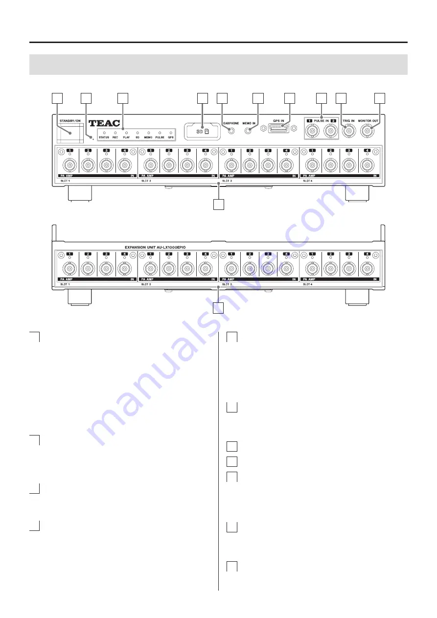
Main unit (LX-1000)
A
B
C
D
E
F
G
H
I
J
K
Expansion unit (AU-LX1000EPIO)
K
E
EARPHONE jack
Connect an earphone here when playing voice
memos.
o
When an earphone is connected, sound will not
be output from the speaker built into the side of
the unit.
F
MEMO IN (mic input) jack
Connect the included mic here to record voice
memos.
G
GPS IN connector
H
Pulse input (PULSE IN) connectors
I
External trigger signal input (TRIG IN)
connector
When using an external contact signal as a trigger to
start and stop recording, input the trigger signal here.
J
MONITOR OUT connector
This can be used to output a monitor signal, which
can be the input signal of any channel.
K
Input/output amplifier module slots
Install input/output amplifier modules here.
A
STANDBY/ON button
Press and hold this button to turn the system on.
Press and hold it again to put the system into standby.
The light shows the status as follows.
Lit blue: Stopped
Blinking blue: Starting up
Lit orange: Power supply voltage abnormal
Blinking orange: Entering standby
Unlit: In standby mode
B
Initialization switch
Use this to initialize the main unit (page 23).
o
Use a long fine pin that fits the hole, such as a large
straightened paper clip, to press this switch.
C
Indicators
These light to show the current status.
See “4-1-1. Indicators” on page 17 for details.
D
SD card slot
Open the SD card slot cover to insert an SD card
(page 23).


