Rev 3
6
of 7
F.
Cleaning
After soldering, removal of fluxes, residues, and activators is necessary. Consult with the supplier of
the solder and flux for recommended cleaning solvents. Cleaners must be free of dissolved flux and
other contaminants. It is recommended cleaning the pc board on its edge. If using aqueous cleaner,
standard equipment such as a soak-tank or an automatic in-line machine should be used. Common
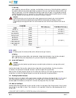
cleaning solvents that will not affect this connector are listed in Figure 3.
DANGER
Consideration must be given to toxicity and other safety requirements recommended by the solvent manufacturer.
Refer to the manufacturer's material safety data sheet (MSDS) for characteristics and handling of cleaners.
Trichloroethylene and methylene chloride is not recommended because of harmful occupational and environmental
effects.
CLEANER
TIME (Minutes)
TEMPERATURE (Max)
NAME
TYPE
ALPHA 2110
Aqueous
1
132°C [270°F]
BIOACT EC-7
Solvent
5
100°C [212°F]
Butyl CARBITOL
Solvent
1
Ambient Room
Isopropyl Alcohol
Solvent
5
100°C [212°F]
KESTER 5778
Aqueous
KESTER 5779
Aqueous
LONCOTERGE 520
Aqueous
LONCOTERGE 530
Aqueous
Terpene
Solvent
Figure 3
NOTE
If a cleaning solvent is not listed, call the number at the bottom of page 1 for advice.
G.
Drying
When drying cleaned assemblies and pc boards, temperature limitations must not be exceeded:
85°C [185°F]. Excessive temperatures may cause connector housing degradation.
3.8.
Connector Placement
CAUTION
Connectors should be handled only by the housing to avoid deformation, contamination, or damage to the contact
solder tines.
Each contact solder tine must be seated on its pc board circuit pad. Optimally, the tines should be
centered on the pc board circuit pads; however, slight misalignment is permissible.
Because the connector alignment posts are for clearance and fit only, the force required to seat the
connector is minimal. The alignment posts and must be inserted into the pc board holes.
3.9.
Checking Installed Connector
All solder joints must conform to the requirements specified in Workmanship Specification
other requirements specified in this document. The solder fillets must be evenly formed around each
contact solder tine. Solder must have 95% minimum coverage over the circuit pad.
3.10.
Removal and Repair
Standard de-soldering methods must be used to remove the connector from the pc board. The connector
must not be re-used after removal. The connector is not repairable. Defective or damaged product must
not be used.
ALPHA, BIOACT, CARBITOL, KESTER, and LONCOTERGE are trademarks of their respective owners.


