


9
DATA AND DEVICES
/ ANT-2.4-WRT-CCC
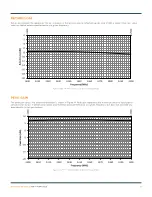
RETURN LOSS
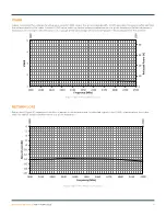
Return loss (Figure 13), represents the loss in power at the antenna due to reflected signals. Like VSWR, a lower return loss value
indicates better antenna performance at a given frequency.
Figure 13 ANT-2.4-WRT Return Loss at Center of Ground Plane
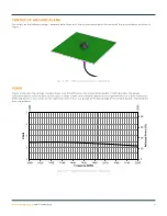
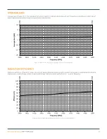
PEAK GAIN
The peak gain across the antenna bandwidth is shown in Figure 14. Peak gain represents the maximum antenna input power
concentration across 3-dimensional space, and therefore peak performance at a given frequency, but does not consider any
directionality in the gain pattern.
Figure 14. AANT-2.4-WRT Peak Gain at Center of Ground Plane
2400
2500
-20
-18
-16
-14
-12
-10
-8
-6
-4
-2
0
2400
2410
2420
2430
2440
2450
2460
2470
2480
2490
2500
Re
tu
rn
Lo
ss
(d
B)
Frequency (MHz)
2400
2500
-20
-15
-10
-5
0
5
10
2400
2410
2420
2430
2440
2450
2460
2470
2480
2490
2500
Pe
ak
G
ai
n (
dB
i)
Frequency (MHz)


