


8
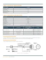
DATA AND DEVICES
/ ANT-2.4-WRT-CCC
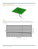
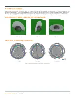
Figure 11. ANT-2.4-WRT Series Antenna at Center of Ground Plane
CENTER OF GROUND PLANE
The charts on the following pages represent data taken with the antenna oriented at the center of the ground plane, as shown in
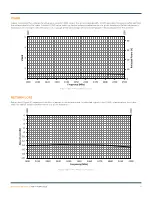
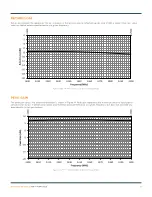
VSWR
Figure 12 provides the voltage standing wave ratio (VSWR) across the antenna bandwidth. VSWR describes the power
reflected from the antenna back to the radio. A lower VSWR value indicates better antenna performance at a given frequency.
Reflected power is also shown on the right-side vertical axis as a gauge of the percentage of transmitter power reflected back
from the antenna.
Figure 12. ANT-2.4-WRT Antenna VSWR at Center of Ground Plane
2400
2500
0
10
20
30
40
1
2
3
4
5
2400
2410
2420
2430
2440
2450
2460
2470
2480
2490
2500
Ref
lec
ted
P
ow
er
(%
)
VSW
R
Frequency (MHz)


