background image

408-2710 

Rev

 H


of 10


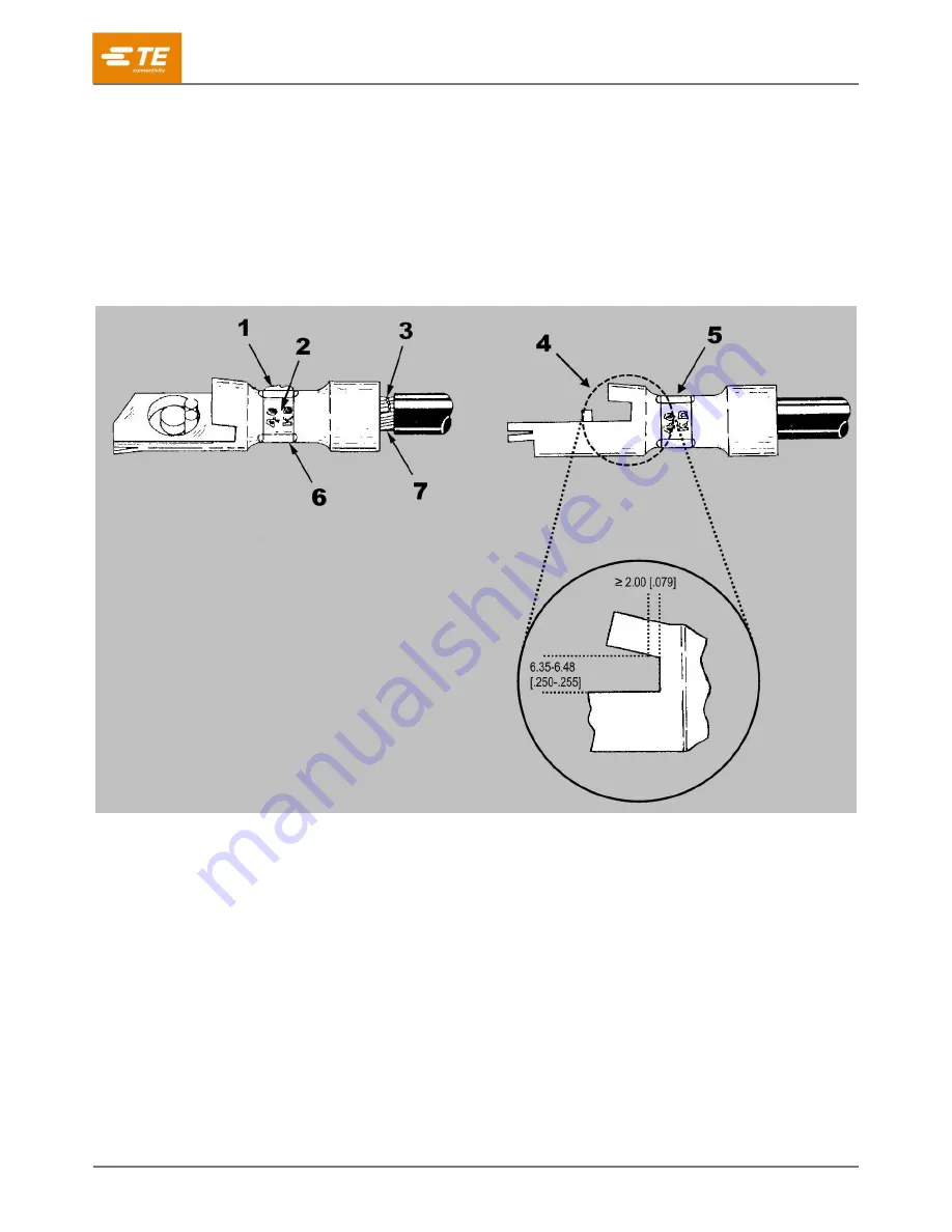
Figure 6 shows problems that mean a crimp should be rejected. Most of these are the caused by a terminal 
that is not properly aligned with the dies. Avoid unacceptable crimps by carefully following the procedures in 
section 4 and performing regular tool maintenance (section 6). 

As shown in Figure 6, the large slot in the terminal must meet the following requirements: 


The height of the slot must be 6.35 to 6.48 mm [.250 to .255 in.]. 


At least 2.00 mm [.079 in.] of slot flat must exist. 

If the slot is spread open too far, you can correct this by squeezing it in a vise. 

Figure 6: Reasons to reject a crimp 


Excessive flash. Damaged dies or wrong wire, terminal, or tooling combination was used. 

Embossed wire size does not match size stamped on terminal or CMA of wire. 

Strands are nicked or missing. 

Large slot is deformed (spread open). 

Incorrect crimp orientation. 

Crimped too far off center, causing large slot to spread open. 

Wire was not inserted far enough into terminal. Wire insulation did not enter insulation barrel. 


Содержание AMPOWER 68361-1

Страница 1: ...our website at www te com 408 2710 18 NOV 2022 Rev H 1 INTRODUCTION AMPOWER Crimping Die Assemblies 68361 1 68253 1 68304 1 and 59867 1 shown in Figure 1 are designed for use in DYNA CRIMP Crimping H...

Страница 2: ...8 1 625 Height 73 76 2 904 Each die assembly when installed in the crimping head crimps AMPOWER Quick Disconnect Terminals onto standard wire sizes as listed in Table 3 These instructions provide spec...

Страница 3: ...avoid injury while operating the power unit exercise caution when holding terminals or wires near the crimping area 1 Select a wire of the correct size and insulation diameter for the terminal see Tab...

Страница 4: ...inst locator 2 Quick disconnect pins must be on this side of locator 3 Moving die 4 While holding the terminal in position activate the power unit so that the moving die advances just enough to hold t...

Страница 5: ...mped on terminal and CMA of wire 2 Crimp is located on wire barrel as shown Table 4 3 Insulation enters insulation barrel 4 Distance from edge of terminal feature to center of crimp Table 4 5 Vertical...

Страница 6: ...6 35 to 6 48 mm 250 to 255 in At least 2 00 mm 079 in of slot flat must exist If the slot is spread open too far you can correct this by squeezing it in a vise Figure 6 Reasons to reject a crimp 1 Ex...

Страница 7: ...ly production Daily Daily occasional Weekly Weekly Monthly Before using the dies wipe off excess oil particularly from the crimping area Oil transferred from the crimping area onto terminations can af...

Страница 8: ...lug gage refer to instruction sheet 408 7424 Figure 7 Recommended plug gage design 1 GO diameter 2 NO GO diameter 3 Wire barrel crimping chamber 4 GO element 5 NO GO element Table 6 Gage diameters Cri...

Страница 9: ...ping chamber The GO element must pass completely through the crimping chamber 5 Gage the wire barrel crimping chamber with the NO GO element in the same manner as step 4 The NO GO element can start en...

Страница 10: ...e to CUSTOMER SERVICE 038 035 TE CONNECTIVITY CORPORATION PO BOX 3608 HARRISBURG PA 17105 3608 For customer repair services call 800 522 6752 Figure 9 Replacement parts Table 7 Die set and component p...

Отзывы: