409-35001
Rev C
60
of 92
“Connector Drag Enabled/Disabled”
–
Toggle this button
to “Enabled” to allow the user to drag and
drop connectors in the part viewer to set their x and y location on the board. To prevent accidental
modification of connector locations, toggle the button to “Disabled”.
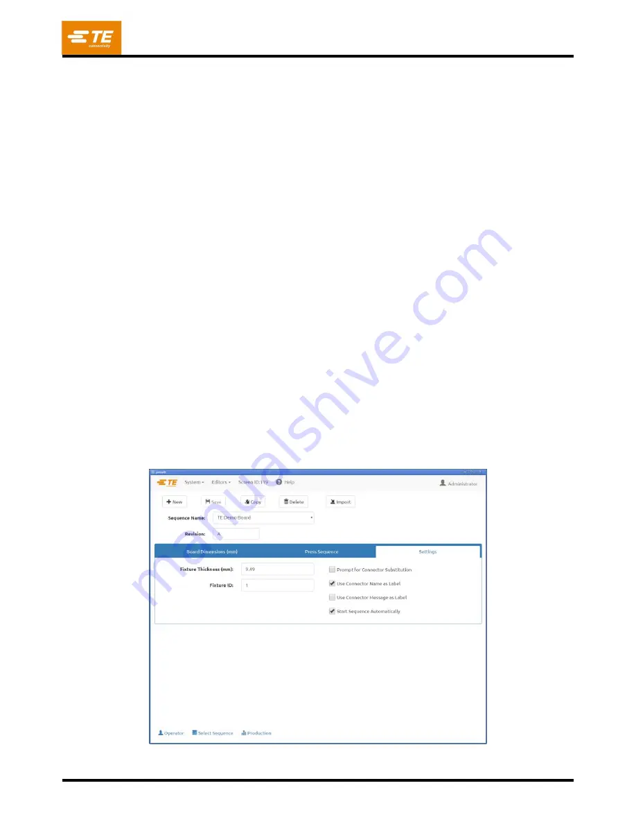
Settings Tab
“Fixture Thickness”
- This is
the thickness of the fixture or “platen” that supports the board. It must be
accurately measured in order for press to height to be accurate.
“Fixture ID”
–
This feature is intended to verify that the correct fixture (support platen) is used with the
PCB. Entering text into this field does not change anything operationally with the press sequence, but may
be useful for traceability and identifying press sequences for MES systems.
Verification of the fixture ID can be added to the press sequence using the “Verify Fixture ID” condition
from the condition database. Initial setup of this condition must be performed by TE field service
personnel.
“Prompt for Connector Substitution”
–
This check box enables substitution connectors to be selected
at run time. For example, manufacturer “A” may be the prime source for a given connector, but “B” is also
approved as interchangeable on this board. If this box is checked, the operator will be offered a selection
of possible alternates for the connector at run time. Their selection will drive the tool and profile selected
for pressing that connector.
Thus, it is possible to press an alternate connector that requires a different tool and different profile than
the primary connector. The alternates are associated with each other by “substitution codes” that are
defined in the connector database. The associated connectors are individually entered into the database,
but they are
“linked” by a common substitution code. See the connector editor for details on entering
connector substitution codes.
“Connector Name as Label”
–
When this feature is checked, each connector’s Name text (from the
connector database) will be displayed with the connector number on each connector in the runtime PCB
drawing. This option takes priority over the “Use
Connector Message
as Label” option.
“Use
Connector Message
as Label”
–
When this feature is checked, the text entered in the Message
field for each connector position will be displayed with the sequence number on each connector in the
runtime PCB drawing.
Figure 61
Содержание 2216055
Страница 34: ...409 35001 Rev C 34 of 92 Figure 35 Figure 36 ...
Страница 71: ...409 35001 Rev C 71 of 92 Figure 77 ...
Страница 72: ...409 35001 Rev C 72 of 92 Figure 78 Figure 79 ...
Страница 75: ...409 35001 Rev C 75 of 92 Figure 82 Figure 83 ...


