background image

p/n 725.0001  REV 1.5 


     © 2021 TCW Technologies, LLC. 


Product Details and General Information: 


The Charging System:


The IBBS automatically maintains its internal battery pack.  The internal charging circuit 
monitors the state of the internal battery and recharges the battery as necessary when the 
aircraft is operational.  The input current for battery recharging is nominally 3.3 amps.  
Battery charging only occurs when the aircraft supply bus connected to pin 5 is above 13.7 
volts. (charging only occurs when the aircraft alternator is running and has available capacity) 
 
If the internal battery is fully discharged for any reason it may require up to 90 minutes of 
recharge time with the normal aircraft bus on.   NOTE: Do not attempt to recharge the IBBS 
product by using an external lead-acid type battery charger directly connected to the input of 
the IBBS.  Battery chargers typically provide pulsating voltages that may damage the IBBS 
product if the system is not connected to a typical primary aircraft battery.  
 
Recharge time at normal temperatures:  0C° to 40 C°    90 minutes nominal 
Recharge time at low temperatures:      -18C° to 0 C°     n 15 minutes preheat 


    -40 C° to -18C°  n 60 minutes preheat 


Back-up Power Master Switch: 

The IBBS has one input switch connection as identified in the wiring diagrams: Back-up 
Power Master.  This switch enables back-up power from the IBBS system to be available on 
the output wires when power on the normal aircraft bus falls below 11 volts.   Pin 1 is pulled 
to ground when the back-up master switch is turned on, this enables the IBBS system. 
   
If the back-up power master switch is enabled and normal aircraft power falls below 11 volts 
then the internal back-up battery will be connected to the outputs and be utilized to supply 
back-up power to the connected load. 
 
If the normal aircraft power bus is above 11 volts, then the outputs are energized with normal 
aircraft power (if the pass thru-power connections are utilized) and the back-up battery 
remains off-line.  The pass thru power feature does NOT depend on the state of the back-up 
master switch.   If power is made available on the pass-thru power inputs, it will pass through 
and be available on the outputs.  This allows for automatic pass through of power during 
normal operation. 


Ground Based Recharging: 

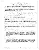
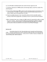
To accomplish ground based charging, connect  an approved battery charger or DC power 
source (set to 14 volts) to the main aircraft battery and energize the main aircraft power bus 
by turning on the master switch, leave all other aircraft loads in their off state.   Note, the 
ground base source of power must be capable to supply the load current of all devices that 
can not be turned off in this nominal state, plus the 3.3 amps of IBBS recharge current.  
Leave the ground-based charging system connected and powered until the IBBS system 
completes its recharge cycle of its internal battery.   See page 5 for details on battery 
charging time.  If voltage monitoring of pin 2 of the IBBS is available a peak charging voltage 
of 14-15 volts will be observed as the battery reaches full capacity. 
 

Содержание IBBS-12v-6ah-CRT

Страница 1: ...back up power to critical electronic loads such as EFIS GPS Autopilots Radios and engine monitor systems Integral to the IBBS is a lithium iron phosphate battery pack and a matched charging system to...

Страница 2: ...ElectroAir electronic ignitions IBBS must be installed using the current aircraft standards and practices as shown in AC 43 13 2A 1B IBBS products are covered by US Patent 8 189 305 Table of Contents...

Страница 3: ...he IBBS must be connected to the back up power input of the respective device For equipment having only a single power input terminal the IBBS pass thru power function must be utilized This is typical...

Страница 4: ...aths feeding the connected loads These pins are internally wired in parallel it is recommended to populate all three pins join the wires together and feed all of these inputs from the pass thru power...

Страница 5: ...he following EFIS systems wire pin 2 to the Volts2 input of the EFIS or engine monitor as follows 8 Complete the installation of the wiring harness and connector prior to attaching the connector to th...

Страница 6: ...aircraft bus falls below 11 volts Pin 1 is pulled to ground when the back up master switch is turned on this enables the IBBS system If the back up power master switch is enabled and normal aircraft p...

Страница 7: ...city at Low Temperatures 18 C 75 of effective nominal capacity 30 C 70 of effective nominal capacity 40 C 45 of effective nominal capacity Servicing The internal battery in the IBBS system is replacea...

Страница 8: ...Master Switch ensure the connected equipment remains energized The low voltage warning light should go out If a separate avionics bus is utilized this may need to be turned ON to continue the operatio...

Страница 9: ...from the IBBS product 4 Measure and record at least the following information The time until the first piece of connected equipment no longer functions or the time until the output of back up power s...

Страница 10: ...h 2 Select engine operation based on the use of only the electronic ignition module provided with back up battery power 3 PULL the circuit breaker feeding pins 4 5 of the IBBS system confirm engine co...

Страница 11: ...gine is properly returned to the off position by following normal run and shut down procedures 10 After completing these tests recharge the IBBS product by operating the system normally for up to 1 5...

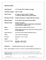
Страница 12: ...volts Charger Integral high performance fast charger with cell balancing and thermal monitoring Surge Protection 34 volt active clamp 1500w 10 1000uS waveform Wiring 15 pin male D sub on product Encl...

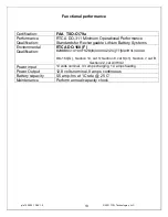
Страница 13: ...e Lithium Battery Systems Environmental Qualification RTCA DO 160 F B2BBBSC1XYXXFSZB IX XXXXAZ ZC TT MA3H3L3XXAX DO 160 G Section 14 cat S Section 8 cat S c1 Section 7 cat B Section 22 cat A3H3L3 Powe...

Страница 14: ...wiring harness View from back of connector Pin Function 5 PWR in charge sensing 2 Batt info 3 Low Volt Warn 12 Output 13 Output 14 Output 15 Output 6 Pwr pass thru input 1 Enable backup switch 9 Groun...

Страница 15: ...725 0001 REV 1 5 2021 TCW Technologies LLC 15 Product mounting footprint 4 mounting holes 0 190 1 50 7 25 2 290 7 70 Top View 0 225 All dimensions in inches Product height 2 75 C G at center of all a...

Страница 16: ...12V 6AH CRT Input 10 15 volts DC Output 12 volts 8 amps INTEGRATED Back up Battery SYSTEM Back up power output 20 awg 10 amp Main Aircraft Bus charge sense pass thru Pin Function 15 pin Male Dsub on u...

Страница 17: ...er Battery Info Back up power output 20 awg 22 awg 22 awg 20 awg 20 awg 20 awg 1 6 9 10 2 5 12 main power input 15 pin female Dsub connector 3 Low Voltage Warning LED NOTE Use redundant ground pins 9...

Страница 18: ...0 awg 20 awg 1 6 9 10 2 5 12 Main power input 15 pin female Dsub connector 3 Low Voltage Warning LED NOTES 7 11 10 amp 8 13 14 15 output output output Back up power input 3 Use of power pins will powe...

Страница 19: ...00 ft 15 000 temp variation 5 Category B Humidity 6 Category B operational shock 7 Category B vibration 8 Category S curve C explosion 9 Category X waterproofness 10 Category Y fluid susceptibility 11...

Страница 20: ...designed and manufactured RETURN OR REPLACED COMPONENTS any item to be replaced under this Warranty must be returned to TCW Technologies in Emmaus PA or such place as TCW may designate freight prepaid...

Отзывы: