p/n 725.0001 REV 1.5
© 2021 TCW Technologies, LLC.
3
Limitations:
The conditions and tests for TSO approval of this article are minimum performance
standards. Those installing this article, on or in a specific type or class of aircraft must
determine that the aircraft installation conditions are within the TSO standards. TSO articles
must have separate approval for installation in an aircraft. The article may be installed only
according to 14 CFR part 43 or the applicable airworthiness requirements.
This article may not be installed as the sole source of power for an instrument or avionic
device that has no other redundancy in the aircraft.
(i.e., If an aircraft has one and only one vhf radio
it must have an additional source of power beside the IBBS system to qualify for installation.)
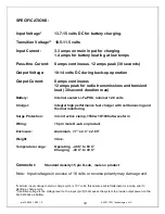
See page 13 for Performance Specifications and potential limitations and ratings under
various conditions, including environmental and application installations. See Item 3 below
for installation location limitations.
Installation Instructions:
1.
IMPORTANT NOTE:
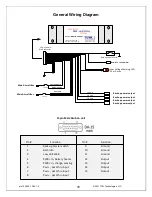
Consult the attached wiring diagrams to identify wiring connections appropriate to the
particular installation. Please note, some equipment such as GPS’s and EFIS systems may
be provided with multiple power inputs. These inputs are often identified as
“Aircraft Power
2
”. For these installations the output of the IBBS must be connected to the “back-up” power
input of the respective device. For equipment having only a single power input terminal the
IBBS pass-thru power function must be utilized. (This is typical of devices such as comm
radios, transponders, autopilots, fuel pumps, and electronic ignitions) The IBBS system
may be fed from a bus that remains active during engine starting, such as the master bus or
it may be fed from an avionics bus that is switched off during engine starting..
2.
Check that the total connected load (summed value of all four output wires of the
IBBS) is less than the following product ratings:
IBBS-12v-6ah-CRT: 8 amps maximum continuous current
12 amps peak for radio transmissions and transient loads*
*(30 seconds max duration)
3.
Mount the IBBS to structure in a suitable location in the aircraft utilizing the practices
identified in AC 43.13-2A/1B. Ensure the mounting points and fasteners are suitable for the
weight of the product, consult the specifications for details. The IBBS must be mounted
inside the aircraft, do not mount the IBBS in the firewall forward area. Do not mount the
IBBS unit up under the instrument panel unless the panel is properly ventilated to ensure
heat does not build up in the area. Select an area that is accessible to allow for future
battery servicing. The preferred operating temperature range of the system is -40 C° to
60 C°, the effective charging temperature range is -40 C° to 40 C° with extended charging
times below 0 C°. Select an installation location that takes these temperatures into
consideration.


