background image

2800 Laura Lane • Madison, WI 53562  |  800.288.9383 • fax: 608.836.9044  |  www.tcsbasys.com  

3

MOUNTING 

& CONNECTIONS

The QD2040b is designed to be hung on a wall using the included mounting bracket and mounting screws . It may also be 

set on a shelf or table . Do not allow the mounting screws to touch the circuit board inside the enclosure . 

When selecting a location to mount the QD2040b, be sure to allow space for cable connections . Locate the QD2040b 

away from excessive dust, heat sources, moisture, or direct sunlight . The ideal environment is a server room . The tem-

perature of the room cannot exceed 77ºF (25ºC), good ventilation is mandatory .

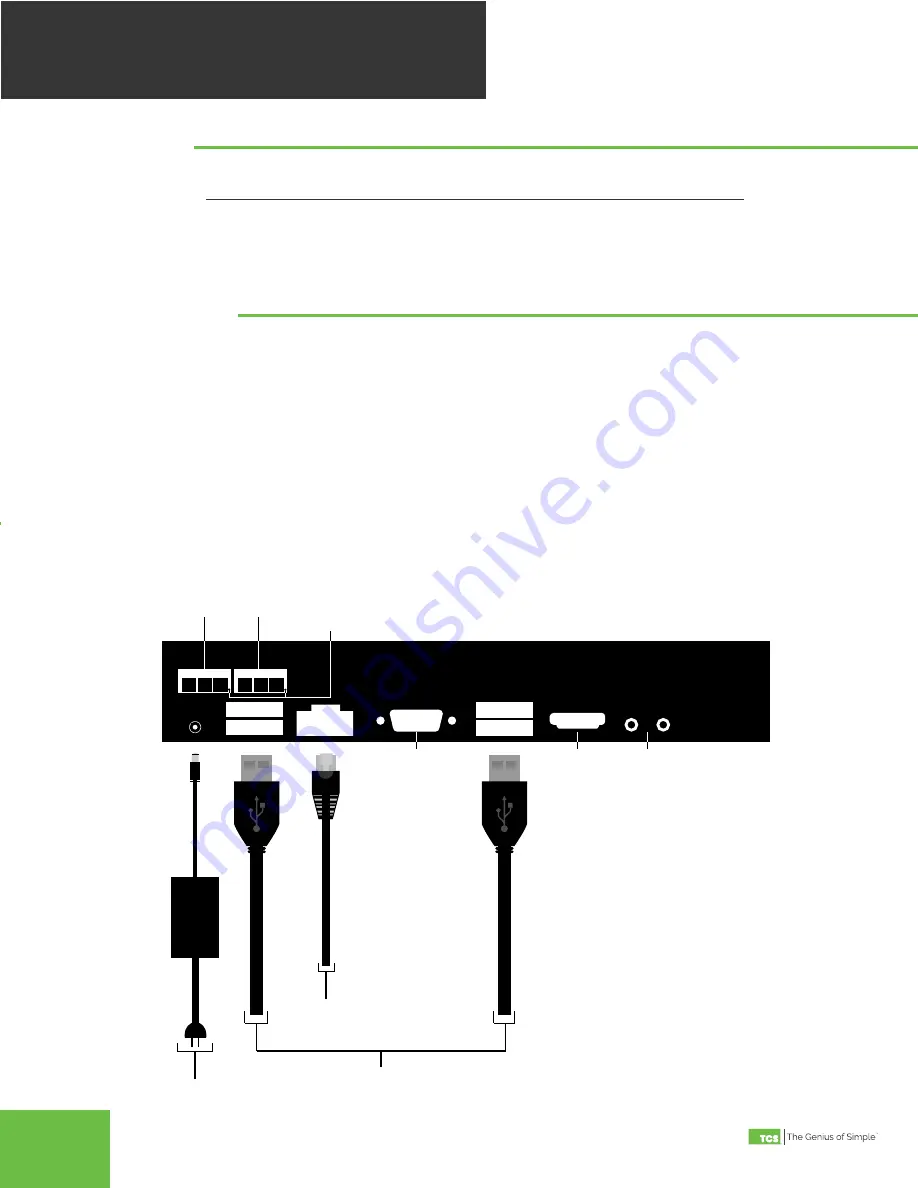
COM 1-2

: Connect an RS-485 Network (Refer to RS-485 Controller Network Wiring & Setup below)

USB PORT 1-4

: Connect an RS-485 Network via a USB to RS-485 converter (QD1010), or connect a TCS ZigBee network 

via a wireless gateway (QW1010) . Refer to RS-485 Controller Network Wiring & Setup below . 


Power

: Attach the included power supply to the back unit and insert the power plug into a 120 VAC socket . Upon connec-

tion the unit may power up automatically . If it does not, press the power button . 


Ethernet

: Connect an Ethernet cable to the specific port on the specified switch on the LAN (this information is deter

-

mined by your local network administrator or IT department) . If a cellular modem is used, connect the Ethernet cable to 

the Ethernet port on the Cellular Modem .

Remaining connections are unused and should not be plugged in .

Mounting

Connections

P

O

WER

C

ORD

USB

CABLE

USB

CABLE

ETHERNET

CABLE

COM 1

COM 2

REF

REF

B

B

A

A

USB PORT 2

USB PORT 1

USB PORT 3

USB PORT 4

ETHERNET

VIDEO

AUX VIDEO

POWER

(12VDC)

Rx/Tx Activity LED’s

To RS-485 Converter 

(QD1010)

To Wall Outlet

To Internet

To Controllers

Not Used

Not Used

Not Used

QD2040b Connections Diagram

Содержание Ubiquity QD2040b

Страница 1: ...WI 53562 800 836 9044 fax 608 836 9044 www tcsbasys com Rev 0617 The QD2040b Ubiquity Cloud Site Gateway connects the site controller network with the Ubiquity Cloud server QD2040b Ubiquity Cloud Site...

Страница 2: ...tines Supervisory override strategy Auto discovery of networked controllers Two integrated RS 485 serial ports Additional serial ports can be added via USB ports Integrated Ethernet controller with fi...

Страница 3: ...er QD1010 or connect a TCS ZigBee network via a wireless gateway QW1010 Refer to RS 485 Controller Network Wiring Setup below Power Attach the included power supply to the back unit and insert the pow...

Страница 4: ...wiring to earth ground TCS recommends a 250 milliseconds time out period for all wired networks and 1000 milliseconds for wireless networks If you encounter timeout errors please contact tech support...

Страница 5: ...a to the actual server Application Options You must select a Network Polling Cycle Time for the QD2040b This is the time interval that the unit will poll the entire network of controllers on all ports...

Страница 6: ...o be used When using static IP it is necessary to enter the IP Address Gateway Subnet DNS1 and DNS2 settings Virtual IP can be used typically left blank The IP settings will need to be established by...

Страница 7: ...ser interface at this point Clicking the green button with the arrow on it on the right side of the Ubiquity Connection Status title bar will refresh the connection status COMMISSIONING TOOLS Commissi...

Страница 8: ...the network must have a unique address excluding the reserved address 248 Network wiring should also be checked The LEDs on the QD2040b indicate the current operating status of the QD2040b POWER This...

Отзывы: