R
2800 LAURA LANE • MIDDLETON, WI 53562 • (800) 288-9383 • FAX (608) 836-9044 • www.tcsbasys.com
3
Setup
note:
If using remote sensor(s), the calibra-
tion may need to be adjusted. See “Checkout and
Troubleshooting” section.
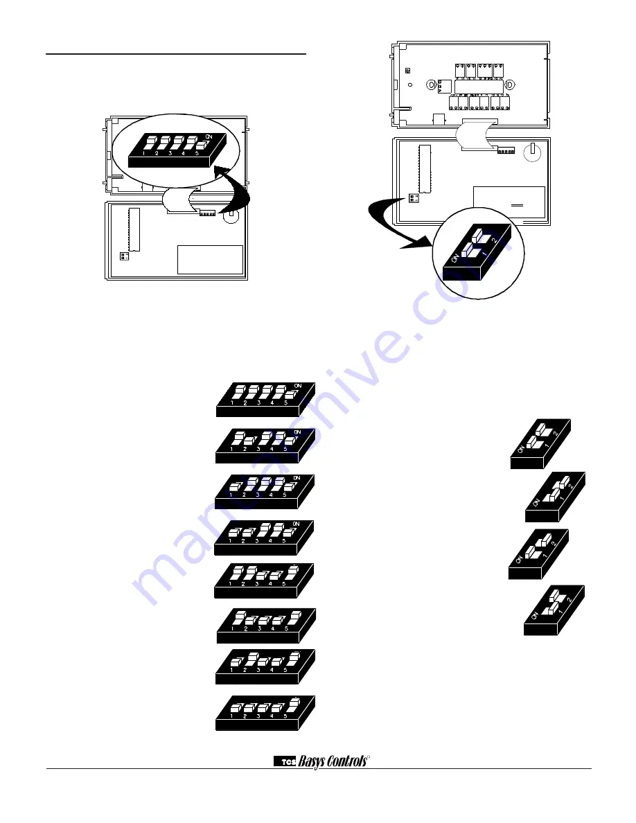
temPeRAtURe SenSoR SeleCtion
The dipswitches in the cover (shown above) must be
set when using remote room, discharge, and/or outdoor
sensors.
Use the following guide to determine the dipswitch set-
tings for your application.
Using built-in room sensor only.
(this is the default setting.)
Using built-in room sensor with
discharge air sensor only.
Using built-in room sensor with
outdoor air sensor only.
Using built-in room sensor with
both discharge and outdoor air
sensors.
Using remote room sensor only.
Using remote room sensor with
discharge air sensor only.
Using remote room sensor with
outdoor air sensor only.
Using remote room sensor with
both discharge and outdoor air
sensors.
KeyPAd ACCeSS
The dipswitches in the cover (shown above connected
with ribbon cable) must be set in order to lock the user
out of programming and/or to set the clock and sched-
ule. Use the guide below to set these dipswitches for
your application. User access may also be limited with
an access code set in programming. (The fan and sys-
tem switches are enabled or disabled in programming
only, and require no dipswitch placement.)
Keypad access to both program-
ming and clock setup. (this is the
default setting.)
no keypad access to programming
or clock setup.
Keypad access to programming
only.
Keypad access to clock setup only.
Once the dipswitches have been set and you have con-
firmed that the sensors are reading correctly (and pro-
gram and clock setup are finished, if locking out access
with dipswitches), secure the cover to the base with the
two set screws located at the top right and the left side
to prevent tampering.
1 2 3 4 5
1 2 3 4 5
REF A
B


