background image

MSD Manual 

2.0 General Information


5


Product Description 

The MotorShield™ is a 3-phase low-pass sine wave filter designed and developed by TCI to 

deliver conditioned power to motor loads driven by PWM drives with switching frequencies from 2 

kHz to 16 kHz. Any drive control parameter which has the effect of reducing the carrier or 

switching frequency below 2 kHz at any time must be disabled. Some sine wave or long lead 

mode drive parameters or operating modes can have this effect. This filter is suitable for VFD 

drives configured to Volts per Hz modes only. Available for three phase voltage systems up to 

460/480 Volts, the MotorShield™ is a passive LC filter connected in series with the output 

terminals of the variable frequency drive. This design removes the carrier frequency distortion 

from the output voltage waveform resulting in a nearly pure sine wave voltage profile. 
The MotorShield™ sine wave filter reduces the effects of the reflected wave phenomenon (dV/dt), 

which can cause motor heating, insulation damage, and excessive audible noise. The reduction 

of high frequency VFD output currents extends the life of motors and transformers and eliminates 

the need for special motor cables. The MotorShield™ reduces VFD ground fault problems and 

noise interference in transducer signals caused by stray high frequency harmonic currents. 
The MotorShield™ is available in a UL Open Type and Type 1 and Type 3R enclosures which 

can be mounted adjacent to the VFD.  
The MotorShield™ consists of the following standard features and components: 

  An L-C power filter circuit with: 

  A TCI 3-phase reactor 

  High-endurance, harmonic-rated capacitors 

  Compression terminals for ease and integrity of all power wiring 

  Thermal switches on reactor and capacitor                                                                                     

  Suitable for all lead lengths extending up to 15,000 feet 


Содержание MotorShield MSD0009A300

Страница 1: ...allation Operation and Maintenance Manual TCI LLC W132 N10611 Grant Drive Germantown WI 53022 Phone 414 357 4480 Fax 414 357 4484 Helpline 800 TCI 8282 www transcoil com 2019 TCI LLC All right reserved Product No 29343 Effective 10 15 19 Version F ...

Страница 2: ......
Страница 3: ...ion 12 Variable Frequency Drive Settings 12 Environment 12 Working Space 12 Power Wiring 12 Thermal Switch 13 Optional Features 13 4 0 Installation Guidelines 14 Wiring 14 Before Connecting 14 Over Temperature Switch 14 Field Wiring Connection Terminals 14 Connection Diagram 16 Grounding 16 Power Wiring 16 5 0 Operation 17 Variable Frequency Drive Settings 17 Start Up Commissioning 17 Before Apply...

Страница 4: ...drawings in Section 6 6 16 17 E Updates to Product Ratings and Dimensions Table Updates to Installation Checklist 9 18 17 F Revision of technical specifications and overall reformat 1015 19 We strive to provide the most up to date and accurate documentation available at the time of printing Please visit www transcoil com for the most recent revision of this manual ...

Страница 5: ...tion readers about conditions which can if proper steps are not taken lead to a serious fault condition physical injury or death Cautions are used to draw attention to instructions Failure to properly follow such instructions may lead to a malfunction and possible equipment damage Warnings Readers are informed of situations that can result in serious physical injury and or serious damage to equipm...

Страница 6: ... Verify with a voltmeter to make sure that all sources of power have been disconnected and that all capacitors have discharged before beginning work Caution The drive output terminals MotorShield and the motor cables are at a dangerously high voltage when power is applied to the drive regardless of motor operation Warning All wiring must be in accordance with the National Electrical Code NEC and o...

Страница 7: ... checklist for a successful installation These points are explained in detail in the subsequent sections of this manual Receiving Inspection The MotorShield has been thoroughly inspected functionally tested at the factory and carefully packaged for shipment When you receive the unit you should immediately inspect the shipping Make sure that the installation location is appropriate for the enclosur...

Страница 8: ... is expressly limited at TCI s option to i repair or replacement of that product or ii return of the product and refund of the purchase price Such remedy shall be Buyer s sole and exclusive remedy TCI SHALL NOT IN ANY EVENT BE LIABLE FOR INCIDENTAL DAMAGES OR FOR CONSEQUENTIAL DAMAGES INCLUDING BUT NOT LIMITED TO LOSS OF INCOME LOSS OF TIME LOST SALES INJURY TO PERSONAL PROPERTY LIABILITY BUYER IN...

Страница 9: ... the output voltage waveform resulting in a nearly pure sine wave voltage profile The MotorShield sine wave filter reduces the effects of the reflected wave phenomenon dV dt which can cause motor heating insulation damage and excessive audible noise The reduction of high frequency VFD output currents extends the life of motors and transformers and eliminates the need for special motor cables The M...

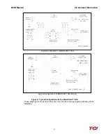
Страница 10: ...on Typical Configuration for MSD 480 V 9A to 16A Typical Configuration for MSD 480 V 23A to 45A Figure 1 Typical Configurations for the MotorShield Filter These drawings are for general reference only Use the drawings supplied with the unit for installation ...

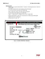
Страница 11: ...al Configuration for MSD 480 V 55A Typical Configuration for MSD 480 V 65A and up Figure 2 Typical Configurations for the MotorShield Filter These drawings are for general reference only Use the drawings supplied with the unit for installation ...

Страница 12: ...age FLA the rated continuous operating current RMS amps System Voltage the maximum VFD output voltage fundamental Hz the maximum VFD output frequency fundamental Phase 3 The MotorShield is designed for use only with 3 phase loads Drawing and Schematic outline and mounting dimension of filter with schematic diagram Manufacturing for TCI internal use Enclosure Type UL Type 1 3R Figure 3 Example of M...

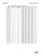
Страница 13: ...ated 110 Amps 480 V Figure 4 MotorShield Model Number Encoding The MotorShield has a current rating rather than a horsepower rating The rating and dimension tables in the following section list the nominal horsepower ratings corresponding to the current ratings of the standard models Standard Product Ratings and Dimension Tables The following table lists the ratings and dimensions of the standard ...

Страница 14: ... 72 cm 645 MSD0130A300 100 130 187 lbs 85 Kg 22 13 in 56 cm 20 43 in 52 cm 28 50 in 72 cm 827 MSD0160A300 125 160 340 lbs 154 Kg 36 00 in 91 cm 28 40 in 72 cm 36 86 in 94 cm 683 MSD0200A300 150 200 425 lbs 193 Kg 36 00 in 91 cm 28 40 in 72 cm 36 86 in 94 cm 1025 MSD0250A300 200 250 450 lbs 204 Kg 36 00 in 91 cm 28 40 in 72 cm 36 86 in 94 cm 1153 MSD0305A300 250 305 460 lbs 209 Kg 36 00 in 91 cm 28...

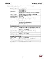
Страница 15: ...ance Maximum peak voltage of output waveform 480 V models 1000 V 600 V models 1 500 V Maximum dV dt of output waveform 480 V models 500 V μs 600 V models 1 500 V μs Environmental Conditions Maximum Elevation 6 600 feet 2 000 m derating required for operation above this level Ambient Operating Temperature Range 30 C 22 F to 40 C 104 F Cooling provisions required for operation above this temperature...

Страница 16: ...roved for such use this equipment is not suitable for use in an explosive atmosphere or in a Hazardous Classified Location as defined in article 500 of the National Electrical Code NEC Make sure that the installation location will not be exposed to corrosive or combustible airborne contaminants excessive dirt of liquids The unit must be installed in an environment where it will not be exposed to C...

Страница 17: ...itors overheat Connect these switches to monitoring equipment Figure 5 Thermal Switches Optional Features Additional wiring requirements may apply to MotorShield units that are equipped with optional features For instructions covering these additional requirements refer to drawings and or other supplemental information furnished with the unit Reactor Thermal Switch Capacitor Thermal Switch ...

Страница 18: ...r Failure to follow the safety instructions set forth in this manual can result in serious injury or death Warning Exercise caution when connecting the filter to the drive Internal filter components may carry dangerous voltage which can cause death or serious injury upon contact Over Temperature Switch A set of over temperature switches is supplied to prevent damage to the filter in the rare case ...

Страница 19: ... 35 lb in 4 0 N m B 30 10 AWG 30 lb in 3 4 N m A 30 10 AWG 40 lb in 4 5 N m B 35 8 AWG 30 lb in 3 4 N m A 35 8 AWG 40 lb in 4 5 N m B 45 8 AWG 30 lb in 3 4 N m A 45 8 AWG 45 lb in 5 1 N m B 55 6 AWG 35 lb in 4 0 N m A 55 6 AWG 45 lb in 5 1 N m C 65 6 AWG 45 lb in 5 1 N m C 65 6 AWG 45 lb in 5 1 N m C 80 4 AWG 50 lb in 5 7 N m C 80 4 AWG 50 lb in 5 7 N m C 110 2 AWG 50 lb in 5 7 N m C 110 2 AWG 50 ...

Страница 20: ... the requirements of the National Electrical Code NEC and or any other codes that apply to the installation site The ground connection must be made using a wire conductor Metallic conduit is not a suitable grounding conductor The integrity of all ground connections should be periodically checked Power Wiring Connect the output of the VFD terminals T1 U T2 V T3 W to the input of the MotorShield ter...

Страница 21: ...configuration Caution Ensure drive output frequency is set between 2 kHz and 16 kHz Failure to do so may result in damage to the filter Caution Thoroughly check the installation before applying power and operating the equipment for the first time Caution The MotorShield can be operated without a load connected to its output terminals for example to facilitate confirmation of system wiring however ...

Страница 22: ...ricians should carry out all electrical installation and maintenance work on the MotorShield Disconnect all sources of power to the VFD and MotorShield before working on the equipment Do not attempt any work on a powered MotorShield Check to see that the installation environment remains free from exposure to excessive dirt and contaminants Refer to the Pre installation Planning section of this man...

Страница 23: ...xceeds its ratings a switching frequency lower than its minimum specification a motor frequency that exceeds maximum specifications or blocked air flow Check to make sure current drive switching frequency and drive output fundamental frequency meet product specifications Check to make sure ventilation openings are open and not blocked or clogged Ensure reactor is not covered with a thick layer of ...

Страница 24: ...rts are needed please contact your TCI representative To ensure that the MotorShield continues to perform to its original specifications replacement parts should conform to TCI specifications Factory Contacts and Tech Support You can contact TCI directly at 800 824 8282 Select Customer Service or Technical Support and have your MotorShield nameplate information available Typical Outline Drawings T...

Страница 25: ...I LLC W132 N10611 Grant Drive Germantown WI 53022 Phone 414 357 4480 Fax 414 357 4484 Helpline 800 TCI 8282 www transcoil com 2019 TCI LLC All right reserved Product No 29343 Effective 10 15 19 Version F ...

Отзывы: