______________________________________________________________________________________________________________________________________________________________________________
__________________
TC Electronic A/S
Gold Channel Service manual
page 14
Circuit Description
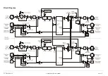
The Gold Channel consist of a front, a digital, an analog and a power supply section. Here is a brief description of the sections:
Front section
consist of three boards and a display, all placed in the front profile. The
big board has two matrix circuits; one for LED's and one for keys. The two encoders
are scanned by IC20 and the two pots are connected dire ctly to the MPU on the main
board. The EEPROM contains the serial no.
The small boards are for LED's and key switches.
Digital section
is placed mainly in the middle and in the left side of the main board.
This section contains the Reset, MPU, SRAM, DSP, DARC, Sound RAM, FLASH,
Interfaces and PLL circuit.
Reset controls the MPU and the DA.
The Software for MPU is loaded into the FLASH. The MPU controls DSP, SRAM, Jeida,
Front, MIDI, External Control In and analog gain settings.
The major task for the DSP is to "calculate" sound. It also generates the 80MHz clock for
the DARC chip.
The DARC chip controls the sound data to/from; DSP, Sound RAM, digital in/outputs,
Word clock Input and AD/DA converters.
Interface for MIDI and External Control In consist almost of discrete components.
The interface for the front has an integrator, which converts a 3.3kHz square wave to a
negative DC voltage for the display contrast. By changing the duty cycle of the square
wave the DC voltage and thereby contrast will also change. An attenuator allows the MPU
to measure the contrast voltage.
The PLL circuit (placed on a separate board) makes a very stable frequency at 256 x sample
rate, this frequency is divided down to 64 x sample rate and to 1 x sample rate by the DARC.
The PLL has its own power regulation.
Analog section
is placed mainly on the right side of the main board.
The analog input is balanced, thus pin 3 should be connected to pin 1 when used with
unbalanced equipment.
Input levels are controlled by digital potentiometers. These potentiometers are located in a
single chip, which controls both the two analog input levels and the two analog output levels.
The A/D converter is a 24bit converter . The A/D and D/A converters have also a separate
power regulation.
The D/A converter is also 24bit. A DC voltage is applied to the left & right signal output at
the converter.
After the D/A comes a 2nd order filter, then the output level and then a 1st order filter.
An electronic balanced circuit perform the output stage. Again XLR pin 3 should be
connected to pin 1 when used with unbalanced equipment.
The Mic. amp is placed on a separate board. This board comes in two versions; P12905-
3
and
P12905-
5
. If the board version is P12905-
3,
make sure it is updated according to the s ervice
notes in appendix.
Power supply section
consist of a separate Power Supply Module and some regulation
circuits on the main board.
One regulation circuit has an electronic switch for the +/-15V. The electronic switch for the
+5V is mounted inside the Power Supply Module. The switches are controlled by the Stand
By circuit. The Stand By circuit is supplied from a separate power wire from the Power Supply
Module.
Phantom power is fed to the Mic. amp board. Here it can be switched on or off.
This service manual does not contain schematics for the Power Supply Module, because any
attempt to repair the module must be completed with some safety tests such as high voltage
and EMC test. Hence it is strongly recommended that the entire Power Supply Module is
replaced in case of malfunction.
Note:
The Power Supply module for the Gold Channel is unique due to the phantom power.
Содержание Gold Channel
Страница 1: ......


