


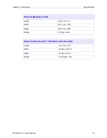


Chapter 2 Installation
Power Supply
TC8619 Rev 1.1User Manual
2-2
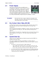
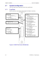
2.4
Power Supply
The TC8619 can be powered by external DC power.
Available power options are 12 VDC, 24 VDC, -48 VDC,
and 125 VDC. There are two terminal block connectors
labeled "PWR A" and "PWR B" only one is required to
power up the unit. Since each TC8619 card is equipped
with a power redundancy capability, the power LEDs on the
front panel will light according to which power jack (A or
B) is connected. Both LEDs will light when power redundancy is utilized.
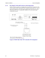
2.5
Dry Contact Alarm Relay (DCAR)
A terminal block connector at the rear panel provides for the Dry Contact Alarm
Relay. This relay can be used in NO (Normal Open) or NC (Normal Close)
configuration.
When used in NO (Normal Open) configuration, the relay will close if the unit loses
power completely or the Alarm is on. The relay remains open during normal
operation.
When used in NC (Normal Close) configuration, the relay will open if the unit loses
power completely or the Alarm is on. The relay remains close during normal
operation.
2.6
System Start Up
Apply the power by plugging the power plug into a power jack (both PWR A &
PWR B for dual power units).
After power is applied, all LEDs (except PWR & VCC LEDs) will flash
momentarily and the following LED status should be observed from the front and
back panels:
1.
The Power "A" and/or "B" and VCC LEDs should be lit.
Note: TC8619 cards installed in the 1U rack chassis will not show the
PWR A LED in the “On” lit state and will be Off. This is normal and the
power to the card will be monitored by the VCC LED being “On” lit.
2.
The "ALM" and "SYNC" LEDs on the front panel will be flashing indicating
that the T1/E1 connection is not established. This is normal when the T1/E1
connection has not been established.
Important
Read and only connect a supply voltage that corresponds to the
type plate of your device. Make sure that the contact load capacity
of the signal contact is not exceeded.


